
The Evolution of Arduino Controllers in Automation
When makers and engineers discuss Arduino controllers in the context of home automation and industrial prototyping, they are referring to the use of Arduino microcontroller boards as the central logic processing unit for switching high-power loads. In 2026, the ecosystem has matured significantly. You can now choose between traditional hobbyist boards like the Arduino Mega 2560 for complex, multi-sensor DIY setups, or industrial-grade PLCs like the Arduino Opta, which bridges the gap between maker projects and factory-floor automation.
This tutorial provides a comprehensive, step-by-step guide to selecting, safely wiring, and programming Arduino controllers to drive electromechanical relays. We will cover critical hardware isolation techniques, non-blocking programming architectures, and edge-case troubleshooting to ensure your automation system is both reliable and safe.
Selecting Your Arduino Controller: Hobbyist vs. Industrial
Before cutting wires, you must match the controller to your project's environmental and electrical demands. Below is a technical comparison of the two most prominent Arduino controllers used for relay automation.
| Feature | Arduino Mega 2560 (Prosumer/DIY) | Arduino Opta (Industrial PLC) |
|---|---|---|
| Microcontroller | ATmega2560 | STM32H747XI (Dual Core) |
| Digital I/O | 54 (15 PWM) | 8 Isolated Inputs / 4 Relay Outputs |
| Relay Output Rating | Requires external relay modules (40mA pin limit) | Internal 10A @ 250VAC (SPST-NO) |
| Power Input | 7-12V DC (Barrel Jack) or 5V USB | 24V DC (Industrial Standard) |
| Typical Cost (2026) | $45 (OEM) / $18 (Clone) | $180 - $240 (Depending on Connectivity) |
| Best Use Case | Multi-zone HVAC, complex sensor arrays | Motor control, industrial conveyor logic |
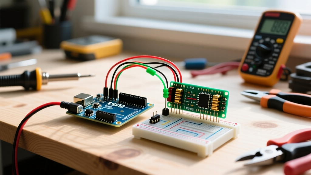
For this tutorial, we will focus on the wiring architecture for the Arduino Mega 2560 using an external 16-channel 5V relay module, as this represents the most common and educational DIY automation scenario. However, the programming logic and isolation principles apply universally across the Arduino controller family.
Step-by-Step Wiring Guide for 5V Relay Modules
The most common point of failure in DIY automation is improper relay wiring, leading to fried microcontrollers or erratic behavior. We will use a standard 16-channel 5V relay module equipped with optocouplers for galvanic isolation.
1. Power Supply and Optocoupler Isolation
Never power a multi-channel relay module directly from the Arduino's 5V pin. Engaging multiple relay coils simultaneously can draw over 1.5 Amps, causing a severe voltage drop that resets the microcontroller or damages the onboard voltage regulator.
- Dedicated Power: Use a separate 5V 3A buck converter or wall adapter to power the relay module's JD-VCC and GND terminals.
- The JD-VCC Jumper: Locate the jumper cap labeled 'JD-VCC' on the relay board. Remove this jumper. This physically separates the relay coil power supply from the optocoupler LED power supply, ensuring true galvanic isolation between your high-voltage loads and your Arduino controller.
- Signal Ground: Connect the Arduino's GND pin to the relay module's 'GND' (the one next to the signal input pins, not the JD-VCC side).
2. Signal Pin Mapping and Flyback Protection
Connect your Arduino digital output pins (e.g., Pins 22 through 37 on the Mega) to the IN1 through IN16 terminals on the relay module. Use 22 AWG stranded wire for these logic signals to resist vibration-induced breakage.
Expert Warning: While most modern relay modules include built-in flyback diodes across the coil, they do not protect against inductive kickback from the load side. If you are switching inductive loads like AC motors or large transformers, you must install a snubber circuit (typically a 100Ω resistor in series with a 0.1µF capacitor) across the relay's Common (COM) and Normally Open (NO) contacts to prevent arc welding. For DC inductive loads, a standard 1N4007 flyback diode wired in reverse bias across the load is mandatory.
For the mains voltage side, use 14 AWG solid copper wire. Ensure all AC connections are housed in a grounded, fire-retardant ABS or polycarbonate enclosure. Never leave exposed mains terminals on a breadboard or open relay shield.
Programming the Controller Logic
When programming Arduino controllers for automation, relying on the delay() function is a critical mistake. Blocking delays prevent the controller from reading emergency stop buttons or sensor inputs while waiting for a relay timer to expire.
Non-Blocking C++ Sketch for Mega 2560
Below is a production-ready snippet utilizing millis() for non-blocking relay control. This allows the Arduino controller to manage multiple timed relays simultaneously while continuously polling safety inputs.
const int RELAY_PIN_1 = 22;
const int EMERGENCY_STOP = 2;
unsigned long previousMillis = 0;
const long interval = 5000; // 5 seconds
bool relayState = false;

void setup() {
  pinMode(RELAY_PIN_1, OUTPUT);
  pinMode(EMERGENCY_STOP, INPUT_PULLUP);
  digitalWrite(RELAY_PIN_1, HIGH); // Active LOW relay module
}

void loop() {
  // Safety check: Immediate shutdown if E-Stop is pressed
  if (digitalRead(EMERGENCY_STOP) == LOW) {
    digitalWrite(RELAY_PIN_1, HIGH); // Turn OFF relay
    return;
  }

  unsigned long currentMillis = millis();
  if (currentMillis - previousMillis >= interval) {
    previousMillis = currentMillis;
    relayState = !relayState;
    digitalWrite(RELAY_PIN_1, relayState ? LOW : HIGH);
  }
}
Industrial Alternative: Arduino PLC IDE
If you upgrade to an industrial Arduino controller like the Arduino Opta, you can abandon standard C++ in favor of the Arduino PLC IDE. This environment supports IEC 61131-3 standard languages, including Ladder Logic (LD) and Function Block Diagram (FBD). Ladder logic is highly preferred in automation because it visually represents electrical relay circuits, making it easier for electricians and maintenance personnel to troubleshoot your code without needing a software engineering background.
Critical Failure Modes and Troubleshooting
Even with perfect wiring, environmental and electrical edge cases can compromise your Arduino controllers. Review these common failure modes and their engineered solutions:
- Relay Contact Welding: Occurs when switching high-inrush loads (like LED drivers or server power supplies) that draw 10x their rated current for the first few milliseconds. Solution: Derate your relay by 50%. If your load draws 5A continuous, use a relay rated for at least 10A, or implement a zero-crossing solid-state relay (SSR) instead of an electromechanical one.
- EMI and Microcontroller Resets: Switching heavy AC loads generates significant Electromagnetic Interference (EMI), which can couple into your logic wires and cause the Arduino controller to brownout or reset. Solution: Route 24V/120V/240V AC wires in separate conduits from your 5V DC logic wires. If they must cross, ensure they cross at a strict 90-degree angle to minimize inductive coupling.
- Optocoupler Degradation: Over years of continuous operation, the internal LEDs in optocouplers degrade, requiring more current to trigger the phototransistor. Solution: Ensure your Arduino digital pins are outputting a clean 5V. If using long wire runs (over 3 meters) to the relay module, the voltage drop may cause unreliable triggering. Use a local logic-level MOSFET to drive the optocoupler inputs instead of relying on the microcontroller's GPIO pins over long distances.
Conclusion
Configuring Arduino controllers for relay automation requires a strict adherence to electrical isolation, proper power budgeting, and non-blocking software architecture. By treating your DIY setup with the same respect for safety and edge-case management as an industrial engineer, you can build automation systems that operate reliably for years. Whether you are wiring a Mega 2560 for a custom greenhouse climate controller or deploying an Opta for a small manufacturing line, the principles of galvanic isolation and inductive load management remain the foundation of robust microcontroller design.