
The Core Concept: Direct Drive vs. TTL Modulation
When makers first search for a laser module Arduino setup, they usually encounter the ubiquitous KY-008 sensor module. While fine for simple optical tripwires, the KY-008 is a direct-drive, 5mW red diode that relies entirely on the Arduino's GPIO pin to source current. This approach completely fails when scaling up to modern 445nm blue/violet diodes used for CNC engraving, light shows, or SLA resin curing.
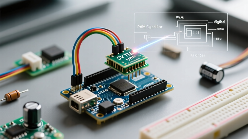
In 2026, the standard for integrating medium-to-high power lasers (500mW to 10W+) with microcontrollers is the 5V TTL (Transistor-Transistor Logic) interface. A TTL laser module contains an onboard constant-current driver and a logic-level MOSFET. The Arduino does not power the laser; it merely sends a 0-5V PWM (Pulse Width Modulation) signal to the TTL pin, instructing the internal driver to switch the diode on and off at microsecond speeds.
Laser Classification and Safety Protocols
Before wiring any diode, you must understand the optical hazards. The FDA classifies lasers based on their potential to cause immediate eye or skin damage. Most Arduino-compatible engraving modules fall into Class 3B (5mW–500mW) or Class 4 (>500mW).
Critical Safety Warning: Class 4 blue (445nm) lasers can cause instant, permanent retinal damage from diffuse reflections. Always use OD5+ (Optical Density 5) safety goggles rated specifically for the 400-450nm wavelength spectrum. Never rely on standard sunglasses or generic green-laser goggles. For comprehensive institutional guidelines, refer to the Stanford Environmental Health & Safety Laser Basics.
Module Comparison: Hobbyist vs. Industrial TTL
Selecting the right module dictates your power supply requirements and thermal management strategy. Below is a comparison of common modules used in the Arduino and GRBL ecosystem.
| Module Type | Output Power | Wavelength | Control Method | Approx. Cost (2026) | Cooling Requirement |
|---|---|---|---|---|---|
| KY-008 (Basic) | 5mW | 650nm (Red) | Direct Drive (Digital) | $2 - $4 | Passive (None) |
| OPT Lasers 500mW | 500mW | 445nm (Blue) | 5V TTL PWM | $45 - $60 | Active (40mm Fan) |
| Endurance 2.1W PRO | 2.1W | 445nm (Blue) | 5V TTL PWM | $130 - $160 | TEC / Active Heatsink |
| Generic 10W Optical | 10W | 450nm (Blue) | 12V PWM / TTL | $80 - $120 | Dual Fan / Air Assist |
Wiring Topology: The 'Common Ground' Imperative
The most frequent point of failure for makers wiring a TTL laser module to an Arduino Uno, Nano, or Mega is neglecting the common ground. Because the Arduino's 5V logic pin is only sending a signal, that signal must have a shared voltage reference with the laser's external power supply.
Step-by-Step Wiring for a 500mW TTL Module
- Power the Diode: Connect a 12V, 3A DC power supply to the laser module's main power input (usually a DC barrel jack or screw terminals marked V+ and GND). Never attempt to power a 500mW+ laser directly from the Arduino's 5V or VIN pins; it will instantly destroy the onboard voltage regulator.
- Establish Common Ground: Run a wire from the 12V Power Supply's GND terminal to the Arduino's GND pin. This is non-negotiable.
- Connect the TTL Signal: Connect the laser's TTL/Signal pin to an Arduino hardware PWM pin (e.g., Pin 9 or Pin 10 on an Uno/Nano).
- Leave the 5V Pin Floating (Usually): Most modern TTL modules draw their logic power internally from the 12V input via a buck converter. Check your specific datasheet; only connect the Arduino 5V to the Laser 5V if the module explicitly requires external logic power.
PWM Frequency and the 'Scalloping' Edge Case
According to the official Arduino analogWrite documentation, the default PWM frequency on pins 9 and 10 is approximately 490 Hz. For blinking an LED, this is fine. For laser engraving using GRBL or custom Arduino G-code interpreters, 490 Hz is catastrophic.
If your laser carriage moves at 1000 mm/min (16.6 mm/sec), a 490 Hz frequency means the laser pulses on and off roughly every 0.033 mm. However, if you are using a dithering algorithm or fast raster engraving, the low frequency causes visible 'scalloping' or dotted burn marks instead of a continuous, smooth line.
The Timer1 Override Solution
To achieve a smooth, continuous burn, you must increase the PWM frequency to at least 16 kHz to 20 kHz. On an ATmega328P (Arduino Uno/Nano), you can manipulate the Timer1 registers directly in your setup() function to achieve a 31.25 kHz PWM frequency on Pins 9 and 10.
// Set Timer1 to 31.25 kHz (Phase Correct PWM, Prescaler 1)
TCCR1A = 0; // Clear Timer/Counter Control Register A
TCCR1B = 0; // Clear Timer/Counter Control Register B
TCNT1  = 0; // Initialize counter value to 0
TCCR1A = _BV(COM1A1) | _BV(COM1B1) | _BV(WGM10); // Phase correct, 8-bit
TCCR1B = _BV(CS10); // No prescaler
Boot-Up Hazards: The Floating Pin Problem
When an Arduino resets or powers on, its GPIO pins float in a high-impedance state before the setup() loop executes. During this brief window (usually 50-200 milliseconds), a connected TTL laser driver may interpret the electrical noise as a HIGH signal, firing the laser at full power unexpectedly. In a CNC environment, this can burn a hole through your material or cause a fire hazard.
The Fix: Always use external pull-down resistors (10kΩ from TTL pin to GND) on the laser signal line, and ensure your code forces the pin LOW immediately.
Example Sketch: Safe Initialization and Fading
This sketch demonstrates safe boot practices, high-frequency PWM configuration, and a basic fade test to verify your TTL wiring.
const int LASER_PIN = 9; // Must be a Timer1 pin for high freq

void setup() {
  // CRITICAL: Force pin LOW immediately to prevent boot-up firing
  pinMode(LASER_PIN, OUTPUT);
  digitalWrite(LASER_PIN, LOW);

  // Initialize Serial for debugging
  Serial.begin(115200);
  Serial.println('Laser Module Arduino Safe Boot Complete.');

  // Apply 31.25kHz PWM override for smooth engraving
  TCCR1A = _BV(COM1A1) | _BV(COM1B1) | _BV(WGM10);
  TCCR1B = _BV(CS10);
}

void loop() {
  // Fade up to 80% power (204 out of 255)
  // Never test at 100% without proper thermal management and safety glasses
  for (int power = 0; power <= 204; power += 5) {
    analogWrite(LASER_PIN, power);
    delay(50);
  }

  // Hold for 1 second
  delay(1000);

  // Fade down to 0
  for (int power = 204; power >= 0; power -= 5) {
    analogWrite(LASER_PIN, power);
    delay(50);
  }

  // Ensure completely off before looping
  digitalWrite(LASER_PIN, LOW);
  delay(2000);
}
Thermal Rollover and Diode Degradation
A common misconception is that a laser module's optical output remains constant regardless of temperature. In reality, 445nm diodes suffer from thermal rollover. As the junction temperature exceeds 60°C, the wall-plug efficiency drops drastically. The module will draw the same electrical current, but the optical output will plummet, and the excess energy is converted into heat, accelerating permanent facet degradation.
If you are designing a custom Arduino-controlled laser system, integrate a thermistor (like an NTC 10k B3950) near the diode housing. Use the Arduino's analog inputs to read the temperature via a voltage divider, and program a hard interrupt to cut the TTL signal if the housing exceeds 55°C. This active thermal protection will extend the lifespan of a $150 diode module from a few dozen hours to several thousand.