
Mastering the MT6701 Read IIC Arduino Interface
The Magn-Tek MT6701 is a highly precise, 14-bit magnetic rotary position sensor widely used in robotics, BLDC motor commutation, and precision steering systems. While it supports SSI and ABZ (quadrature) outputs, many makers and engineers prefer the I2C (often referred to as IIC) bus for its simplicity and low pin-count. However, executing a successful mt6701 read iic arduino implementation requires more than just connecting four wires. It demands an understanding of open-drain bus architectures, specific register mapping, and precise magnetic air-gap tolerances.
In this comprehensive 2026 guide, we will walk through the exact hardware requirements, I2C register bitwise mathematics, and production-ready Arduino C++ code required to reliably extract angle data from the MT6701.
💡 Quick Specs & Market Pricing (2026)
• Resolution: 14-bit (16,384 steps per revolution)
• I2C Address: 0x06 (7-bit) / 0x0C (8-bit)
• Max I2C Clock: 1 MHz (Fast-mode Plus)
• IC Cost: ~$1.80 - $2.50 (bare chip)
• Breakout Board Cost: $9.00 - $15.00 (from vendors like DFRobot or generic marketplaces)
Hardware Requirements and Bill of Materials (BOM)
Before writing code, ensure your physical layer is robust. I2C failures are almost always hardware-related. Gather the following components:
- Microcontroller: Arduino Uno R4, Nano 33 IoT, or ESP32 (Any 3.3V or 5V tolerant board).
- Sensor: MT6701 Breakout Board (SSOP-14 package mounted on a PCB).
- Magnet: 4mm x 2.5mm Radially/Diametrically magnetized cylinder. (Do not use axially magnetized discs; they will not work).
- Resistors: Two 4.7kΩ pull-up resistors (for 100kHz/400kHz I2C buses).
- Wiring: Short, shielded twisted-pair cables if routing >10cm.
MT6701 I2C Pinout and Arduino Wiring
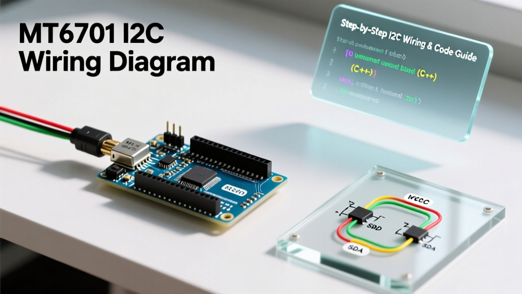
The MT6701 breakout typically exposes VCC, GND, SDA, and SCL for IIC communication. Below is the standard wiring matrix for a 5V Arduino Uno R4 or Nano.
| MT6701 Pin | Arduino Pin | Notes & Requirements |
|---|---|---|
| VCC | 5V (or 3.3V) | Sensor operates from 3.3V to 5V. Match to your MCU logic level. |
| GND | GND | Must share a common ground plane with the MCU. |
| SDA | A4 (Uno) / SDA | Requires a 4.7kΩ pull-up resistor to VCC if not on the breakout. |
| SCL | A5 (Uno) / SCL | Requires a 4.7kΩ pull-up resistor to VCC if not on the breakout. |
The Pull-Up Resistor Rule (Crucial for IIC)
The I2C bus utilizes an open-drain architecture. According to the official NXP I2C-bus specification (UM10204), the bus lines must be pulled high via resistors. Many cheap MT6701 breakout boards omit these resistors to save BOM costs. If your I2C scanner returns no devices, solder 4.7kΩ resistors between SDA-VCC and SCL-VCC immediately. For bus capacitance exceeding 200pF (long wires), drop to 2.2kΩ resistors.
Register Map: Where the Angle Data Lives
Unlike simpler sensors that stream data continuously, the MT6701 requires you to request specific memory registers. The 14-bit angle data is split across two 8-bit registers.
| Register Address | Name | Bit Range | Description |
|---|---|---|---|
| 0x03 | Angle_H | Angle[13:6] | Contains the 8 Most Significant Bits of the angle. |
| 0x04 | Angle_L | Angle[5:0] + 2 Status Bits | Contains the 6 Least Significant Bits (in the upper 6 bits of the byte). |
The Bitwise Math: To reconstruct the 14-bit integer (0 to 16383), you must shift the high byte left by 6 positions, and the low byte right by 2 positions, then combine them using a bitwise OR operator: angle_raw = (reg_03 << 6) | (reg_04 >> 2);
Arduino Code: Reading the MT6701 via I2C
Below is the production-ready C++ code utilizing the native Arduino Wire library. This sketch includes I2C error handling to prevent bus lockups, a common issue in noisy industrial environments.
#include <Wire.h>

#define MT6701_I2C_ADDRESS 0x06
#define REG_ANGLE_H 0x03
#define REG_ANGLE_L 0x04

float current_angle_deg = 0.0;

void setup() {
  Serial.begin(115200);
  Wire.begin();
  Wire.setClock(400000); // Set I2C to Fast Mode (400kHz)

  // Verify sensor presence
  Wire.beginTransmission(MT6701_I2C_ADDRESS);
  byte error = Wire.endTransmission();
  if (error != 0) {
    Serial.println("FATAL: MT6701 not found on I2C bus. Check pull-ups and wiring.");
    while(1); // Halt execution
  }
  Serial.println("MT6701 IIC initialized successfully.");
}

void loop() {
  uint16_t angle_raw = readMT6701Angle();

  if (angle_raw != 65535) { // 65535 indicates an I2C read error
    // Convert 14-bit raw value to degrees (0.00 to 359.99)
    current_angle_deg = (angle_raw * 360.0) / 16384.0;
    Serial.print("Angle: ");
    Serial.println(current_angle_deg, 2);
  } else {
    Serial.println("I2C Bus Error - Retrying...");
  }

  delay(10); // ~100Hz read rate
}

uint16_t readMT6701Angle() {
  Wire.beginTransmission(MT6701_I2C_ADDRESS);
  Wire.write(REG_ANGLE_H);
  uint8_t endTxError = Wire.endTransmission(false); // Repeated start

  if (endTxError != 0) return 65535;

  Wire.requestFrom((uint8_t)MT6701_I2C_ADDRESS, (uint8_t)2);

  if (Wire.available() == 2) {
    uint8_t high_byte = Wire.read();
    uint8_t low_byte = Wire.read();

    // Reconstruct 14-bit angle
    uint16_t raw_angle = (high_byte << 6) | (low_byte >> 2);
    return raw_angle;
  }
  return 65535;
}
Calibration and Magnetic Air Gap Troubleshooting
Even with perfect I2C code, your mt6701 read iic arduino project will fail if the magnetic circuit is flawed. The MT6701 relies on Hall-effect arrays that require a specific magnetic flux density (typically 40mT to 60mT).
Common I2C and Magnetic Failure Modes
- Ghosting / Jumping Values: Caused by using an axial magnet instead of a radial (diametric) magnet. The MT6701 reads the lateral field, not the vertical pole.
- I2C Bus Lockup: Occurs when EMI from nearby BLDC motors corrupts the I2C clock line. Fix: Use twisted-pair shielded cables for SDA/SCL and add a 100nF decoupling capacitor directly across the MT6701 VCC and GND pins.
- Non-Linearity at Edges: Caused by an improper air gap. The physical distance between the top of the IC package and the bottom of the magnet must be strictly maintained between 1.0mm and 2.5mm. Optimal linearity is achieved at exactly 1.5mm.
SSI vs. I2C: When to Switch Protocols
While I2C is excellent for setup and low-speed telemetry (up to 100Hz reliably on standard Arduinos), it is not suitable for high-speed motor commutation. If you are building a gimbal or a high-RPM FOC (Field Oriented Control) motor driver requiring >1kHz update rates, you should abandon I2C and wire the MT6701 in SSI (Synchronous Serial Interface) mode. SSI bypasses the I2C protocol overhead, allowing raw, clock-synchronized 14-bit data streams at speeds exceeding 10kHz.
Frequently Asked Questions (FAQ)
Can I use multiple MT6701 sensors on the same I2C bus?
No. The MT6701 has a hardcoded I2C slave address of 0x06. It does not feature configurable address pins. To read multiple sensors, you must use an I2C multiplexer like the TCA9548A, or utilize the SSI/ABZ outputs for the secondary sensors.
Why does my I2C scanner show address 0x0C instead of 0x06?
Some I2C scanner scripts display the 8-bit address format (which includes the Read/Write bit). 0x06 shifted left by one bit becomes 0x0C. Always use the 7-bit address (0x06) when using the Arduino Wire.h library.
Does the MT6701 require a 3.3V or 5V logic level?
The MT6701 operates natively from 3.3V to 5.0V. If you are using a 3.3V microcontroller (like an ESP32 or Arduino Nano 33 IoT), power the sensor with 3.3V to ensure the I2C SDA/SCL high-states match your MCU's logic thresholds without requiring a logic level shifter.