
The Hidden Cost of Basic Resistive Probes
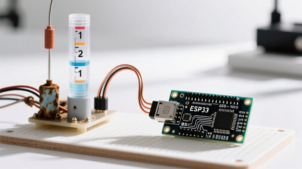
If you have ever built a basic water level detector Arduino project using the ubiquitous $2 resistive fork sensors, you are likely familiar with their fatal flaw: rapid degradation. When a direct current (DC) passes through exposed copper or nickel traces submerged in water, it triggers electrolysis and galvanic corrosion. Municipal water, rich in dissolved minerals, acts as a highly effective electrolyte. In real-world testing, standard resistive probes lose up to 40% of their conductive surface area within 4 to 8 weeks, leading to false readings and eventual open-circuit failures.
While applying an alternating current (AC) or pulsing the DC power via a MOSFET can slow this process, it is merely a band-aid. For any deployment intended to last longer than a few months—such as rainwater harvesting, sump pump monitoring, or hydroponic reservoirs—a hardware migration is mandatory. This guide details how to upgrade your legacy setup to a robust, non-contact IoT architecture.
Sensor Migration Matrix: Choosing Your Upgrade Path
Selecting the right replacement sensor depends entirely on your tank geometry, water chemistry, and budget. Below is a comparison of the three most reliable upgrade paths for industrial and prosumer maker applications.
| Technology | Recommended Model | Avg. Cost (2026) | Range / Depth | Contact Required? | Primary Limitation |
|---|---|---|---|---|---|
| Capacitive | XKC-Y25-V | $9.50 | Point Level (up to 20mm wall) | No (External) | Requires flat, uniform tank wall |
| Ultrasonic | JSN-SR04T (V3.0) | $14.00 | 20cm to 450cm | No (Air gap) | Fails with heavy surface foam |
| Hydrostatic | MPX5700AP + ADS1115 | $16.50 | Continuous (Depth dependent) | Yes (Submerged tube) | Requires 16-bit ADC for shallow tanks |
Path A: Non-Contact Capacitive (XKC-Y25-V)
Capacitive sensors detect changes in the dielectric constant between two plates. Water has a high dielectric constant (~80) compared to air (~1) or plastic (~2.5). The XKC-Y25-V is an industrial-grade, non-contact module that straps to the outside of a PVC or HDPE tank. It can penetrate up to 20mm of non-metallic wall thickness. Pro Tip: Use a high-quality thermal pad or RTV silicone to bond the sensor to the tank, eliminating air gaps that cause erratic triggering.
Path B: Waterproof Ultrasonic (JSN-SR04T)
For large tanks like 1000L IBC totes or deep cisterns, the JSN-SR04T is the standard upgrade. Unlike the cheap HC-SR04, the JSN-SR04T features an IP67-rated transducer separated from the control board by a 2.5-meter cable. However, it has a strict 20cm blind zone. If your water level rises within 20cm of the sensor, it will return a maximum distance error. Furthermore, as noted in the SparkFun Ultrasonic Sensor Hookup Guide, acoustic waves are heavily absorbed by porous materials; if your water surface accumulates more than 2cm of foam or debris, the ultrasonic pulse will scatter, resulting in timeout errors.
Path C: Hydrostatic Pressure (MPX5700AP)
If your tank has irregular geometry, internal baffles, or heavy surface foam, hydrostatic pressure is the only reliable continuous measurement method. By routing a rigid PVC tube to the bottom of the tank and connecting the top to an MPX5700AP pressure transducer, you measure the weight of the water column. Because 1 PSI equals roughly 27.68 inches of water column, a shallow 2-foot tank generates only ~0.86 PSI. The standard 10-bit ADC on an ATmega328P lacks the resolution to read this accurately. You must migrate to a 16-bit I2C ADC like the ADS1115 to achieve sub-millimeter resolution.
Upgrading the Brain: From ATmega328P to ESP32-C3
A true migration involves more than just the sensor; it requires modernizing the microcontroller. The classic Arduino Uno (ATmega328P) draws approximately 45mA at idle. In a remote, battery-powered water monitoring station, this will drain a standard 18650 lithium-ion cell in less than a week.
The ESP32-C3 SuperMini (retailing around $3.50) is the optimal upgrade target. It features built-in Wi-Fi and Bluetooth LE, but more importantly, its deep sleep current drops to roughly 10µA. According to the Espressif IoT Development Framework (ESP-IDF) Sleep Modes documentation, utilizing the ULP (Ultra-Low Power) co-processor or RTC timers allows the ESP32 to wake up, trigger a sensor reading via GPIO, transmit the payload over MQTT, and return to sleep in under 800 milliseconds. This extends battery life from days to several months.
Step-by-Step Migration Workflow
Follow this exact sequence to transition from a legacy resistive setup to a modern IoT node without introducing ground loops or parasitic drain.
- Implement Power Gating: Do not leave sensors powered continuously. Use an N-channel logic-level MOSFET (like the AO3400) to switch the VCC line of your ultrasonic or capacitive sensor. Pull the MOSFET gate HIGH via the ESP32 only during the 50ms measurement window.
- Isolate Signal Lines: If you are monitoring a sump pit with a high-voltage AC pump nearby, electromagnetic interference (EMI) will corrupt low-voltage UART or analog signals. Route your sensor cables in shielded twisted-pair wire and use an optocoupler (e.g., PC817) on the digital output lines.
- Migrate the Codebase: Replace
delay()functions with non-blockingmillis()timers. When using the Arduino SoftwareSerial Library Documentation for UART-based sensors, ensure your ESP32 is awake and the serial buffer is flushed before initiating the trigger pulse. - Integrate MQTT Telemetry: Move away from serial-monitor debugging. Publish your water level data to an MQTT broker (like Mosquitto or HiveMQ) using JSON payloads. Include metadata such as battery voltage (via a voltage divider on ADC pin 3) and Wi-Fi RSSI to monitor node health remotely.
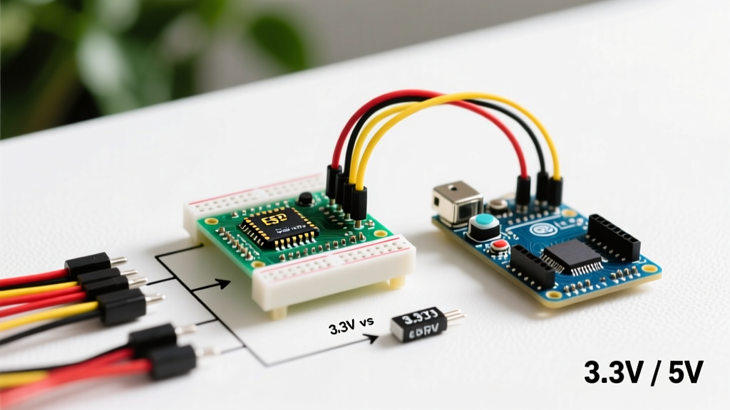
Expert Insight: Never wire a 5V ultrasonic sensor directly to a 3.3V ESP32 GPIO pin without a logic level shifter or a simple voltage divider (e.g., 2kΩ and 3.3kΩ resistors). While many makers report it 'working fine' initially, the 5V echo pulse will slowly degrade the ESP32's internal clamping diodes, leading to unpredictable reboots and eventual silicon failure within 3 to 6 months.
Real-World Edge Cases and Failure Modes
Even with premium hardware, environmental factors can derail a water level detector Arduino project. Anticipate these edge cases during your deployment phase:
- Condensation on Ultrasonic Transducers: In high-humidity environments (like a closed rain barrel), condensation forms on the JSN-SR04T mesh. This alters the acoustic impedance, causing the sensor to read the water level as exactly 20cm (the blind zone) regardless of actual depth. Solution: Apply a hydrophobic nano-coating spray to the transducer mesh, or mount a small 5V silicone heater pad behind the sensor to keep it 2°C above the dew point.
- Mineral Scaling on Capacitive Sensors: If using a submerged capacitive probe rather than an external strap-on model, calcium carbonate buildup will alter the baseline capacitance. Solution: Implement a software calibration routine that establishes a new 'empty tank' baseline once a month during known dry cycles.
- Water Hammer Transients: When a solenoid valve or pump shuts off abruptly, the resulting pressure spike (water hammer) can momentarily register as a massive depth increase on hydrostatic sensors. Solution: Implement a software median filter (taking 5 rapid readings and discarding the highest and lowest) or install a physical snubber/orifice restrictor on the pressure transducer's input port.
Conclusion: The ROI of Upgrading
Migrating your legacy water level detector Arduino setup requires an upfront investment of roughly $25 to $35 in modern components (ESP32-C3, JSN-SR04T or XKC-Y25, and power gating circuitry). However, the return on investment is immediate when factoring in the elimination of monthly probe replacements, the prevention of water damage from failed sensors, and the ability to monitor remote tanks via IoT dashboards. By moving away from direct-contact resistive methods and embracing non-contact physics, you transform a fragile weekend project into a resilient, deployment-ready instrument.