
The Reality of Arduino Prototype Shield Diagnostics
Transitioning from a solderless breadboard to an arduino prototype shield is a major milestone in any maker project. It provides mechanical stability and permanent electrical connections. However, this transition frequently introduces a new class of hardware errors: cold solder joints, power rail misconfigurations, and pin-loading conflicts that cause silent failures or catastrophic component damage. Unlike a breadboard where a loose wire simply falls out, a soldered perfboard error is permanent until you apply targeted diagnostic techniques.
In 2026, with the widespread adoption of the Arduino Uno R4 Minima and WiFi boards alongside the classic R3, the electrical tolerances and logic level architectures have shifted. Diagnosing faults on a prototype shield requires a systematic approach, moving beyond simple visual inspections to electrical measurements and thermal analysis. This guide details the exact failure modes, multimeter testing procedures, and remediation strategies for the most common prototype shield errors.
Symptom-to-Solution Diagnostic Matrix
Before applying power to a newly soldered shield, or when troubleshooting an existing one, use this diagnostic matrix to isolate the root cause of your hardware failure.
| Observed Symptom | Probable Root Cause | Diagnostic Test / Tool | Target Measurement |
|---|---|---|---|
| Board gets hot; 5V rail drops to <4.5V | 5V-to-GND short or AMS1117 thermal throttling | Fluke 117 Multimeter (Continuity / Thermal) | >10Ω between 5V and GND (unpowered) |
| 'avrdude: stk500_recv() error' on upload | D0 (RX) or D1 (TX) loaded down by shield components | Brymen BM235 (Resistance) | >10kΩ between D0/D1 and GND |
| I2C sensors return -1 on bus scan | Bus capacitance >400pF or missing pull-up resistors | Oscilloscope (Rise time measurement) | Rise time <300ns (Standard Mode) |
| Erratic analog sensor readings | High-impedance solder joint or ungrounded shield braid | Visual inspection + Continuity probe | <0.5Ω from sensor GND to Arduino GND |
Deep Dive 1: Power Rail Misconfigurations and Thermal Shutdowns
The most catastrophic errors on an Arduino prototype shield involve power routing. The classic Uno R3 utilizes an AMS1117-5.0 linear voltage regulator to step down the barrel jack input (typically 7V-12V) to 5V. The AMS1117 is rated for 800mA, but this is contingent on thermal dissipation. If you apply 12V to the barrel jack and draw 300mA from the 5V rail on your prototype shield, the regulator must dissipate (12V - 5V) * 0.3A = 2.1 Watts. The SOT-223 package will exceed its 150°C junction temperature and trigger internal thermal shutdown within seconds.
Diagnosing the 'Phantom Brownout'
When thermal shutdown occurs, the 5V rail collapses, the ATmega328P resets, the regulator cools, and the cycle repeats. This looks like a software crash or a brownout bug. To diagnose this:
- Measure the Unloaded Rail: Disconnect the shield. Power the Uno via the barrel jack. Measure the 5V pin. It should read exactly 4.95V to 5.05V.
- Measure Under Load: Attach the shield. If the voltage immediately drops to 3.2V - 4.5V and the regulator is too hot to touch, you have exceeded the thermal budget.
- The Fix: Stop using the onboard linear regulator for high-current shields. Solder a high-efficiency buck converter (like the Pololu D24V50F5, capable of 5A output) directly onto the prototype shield's power bus, feeding it from the
Vinpin.
Deep Dive 2: Upload Failures and Serial Pin Interference
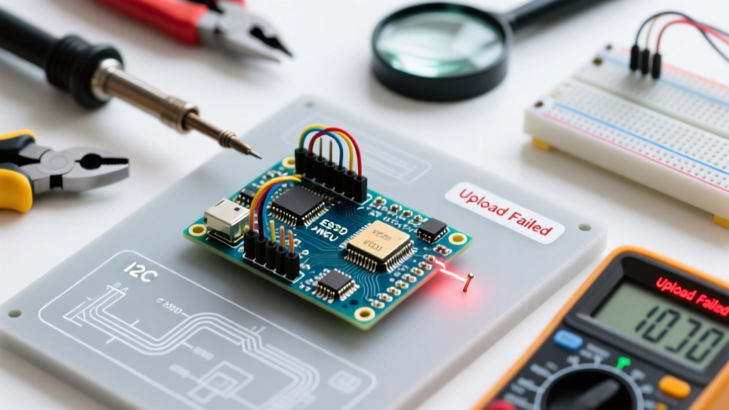
One of the most frustrating errors when using a prototype shield is the inability to upload new sketches, yielding the dreaded avrdude: stk500_recv(): programmer is not responding error. This is rarely a software issue; it is almost always a hardware conflict on the serial lines.
The Arduino Uno uses a dedicated ATmega16U2 chip to handle USB-to-Serial conversion. The 16U2 communicates with the main ATmega328P via pins D0 (RX) and D1 (TX). If your prototype shield design ties D0 or D1 to a low-impedance component—such as a motor driver enable pin, a relay module without optoisolation, or an LED with an undersized resistor—the 16U2 cannot drive the line high or low during the bootloader handshake phase.
Expert Diagnostic Rule: Never route D0 or D1 directly to any inductive load or low-impedance input on a prototype shield. If you must use the serial pins for debugging, route them through a 220Ω series resistor on the perfboard to protect the 16U2 and prevent loading errors during upload.
According to the official Arduino troubleshooting documentation, isolating the shield is the first step. Remove the shield entirely. If uploads succeed, the shield is loading the serial lines. Use your multimeter in resistance mode to measure between D0/D1 and GND on the unpowered shield. Any reading below 5kΩ indicates a design flaw that must be corrected by adding series resistors or shifting the component to software serial (e.g., SoftwareSerial on pins D10 and D11).
Deep Dive 3: Signal Integrity, I2C Capacitance, and Solder Defects
When prototyping I2C sensors (like the BME280 or MPU6050) on a large Adafruit Proto Shield or generic perfboard, wire length and solder quality become critical. The I2C specification limits bus capacitance to 400pF. Long, unshielded 22AWG jumper wires routed across a 4x6 inch prototype shield can easily introduce 50pF to 100pF of parasitic capacitance per trace. When combined with the internal capacitance of multiple sensors, the SDA and SCL lines suffer from slow rise times, causing the microcontroller to misread bits and return -1 on an I2C scanner.
Solder Joint Impedance and Cold Joints
A cold solder joint doesn't just mean a broken connection; it can act as a non-linear resistor or a tiny capacitor. If you are using 63/37 leaded solder, your iron tip (such as the Pinecil V2 running on a 24V power supply) should be set precisely to 320°C. If the temperature is too low, the flux activates but the solder fails to form a proper intermetallic bond with the copper pad, resulting in a high-impedance joint.
- Visual Cue: A good joint is concave and shiny. A cold joint is convex, dull, and grainy.
- Electrical Cue: Set your multimeter to the millivolt DC range. Probe across the suspected solder joint while the circuit is powered and drawing current. A good joint will read 0.00mV. A defective joint will show a measurable voltage drop (e.g., 5mV - 20mV) indicating resistance.
- Remediation: Apply high-quality no-clean flux (like Amtech NC-559-V2-TF) and reflow the joint with a clean, tinned iron tip for exactly 2 to 3 seconds.
Essential Diagnostic Toolkit for 2026
To effectively diagnose errors on an arduino prototype shield, you need tools that go beyond basic continuity checking. Here is the recommended diagnostic loadout for serious hardware troubleshooting:
- Digital Multimeter: Brymen BM235 (~$110) or Fluke 117 (~$230). You need fast continuity beeping and precise millivolt resolution to detect voltage drops across solder joints.
- Thermal Imaging: InfiRay P2 Pro (~$250). Attaches to your smartphone and instantly reveals which component on the prototype shield is drawing excess current or shorting to ground.
- Soldering Station: Pinecil V2 (~$26) with T12-compatible tips. Essential for precise thermal control when reworking mistakes on dense perfboard layouts.
- Logic Analyzer: Saleae Logic Pro 8 or a $15 24MHz 8-channel clone. Mandatory for diagnosing I2C/SPI timing errors caused by parasitic capacitance on long shield traces.
Summary: A Methodical Approach to Hardware Errors
Errors on an arduino prototype shield are rarely random; they are the direct result of electrical physics interacting with physical layout constraints. By understanding the thermal limits of onboard regulators, the impedance sensitivity of the USB-to-Serial bridge, and the capacitance limits of digital communication buses, you can transition from guessing to precise diagnosis. Always verify your power routing before applying external loads, isolate serial pins from inductive components, and treat your soldering temperature and flux application as critical variables in signal integrity. Mastering these diagnostic techniques will drastically reduce your hardware debugging time and result in robust, field-ready prototypes.