
The Hidden Bottleneck in MCU Prototyping
Whether you are prepping 50 Arduino Nano clones for a university robotics lab or assembling custom shields for a small-batch commercial product, soldering Arduino header pins is a notorious workflow bottleneck. An unoptimized approach—holding pins with bare fingers, guessing solder volumes, and reworking cold joints—can stretch a 15-minute batch job into an hour of frustration and burned fingertips.
As we move through 2026, the maker ecosystem has matured. While surface-mount technology (SMT) dominates high-volume manufacturing, through-hole 0.1-inch (2.54mm) pitch headers remain the undisputed standard for modular prototyping. Optimizing your soldering workflow for these components requires a shift from 'hobbyist improvisation' to 'bench-level manufacturing discipline.' This guide details the exact jigs, metallurgical choices, and step-by-step techniques to cut your soldering time by 60% while achieving joints that meet professional reliability standards.
Selecting the Right Hardware for the Job
Not all pins are created equal. The physical geometry of the pin dictates solder flow, mechanical retention, and mating friction. Before firing up your iron, match the header type to your workflow needs.
| Header Type | Post Geometry | Best Use Case | Solder Flow & Workflow Impact |
|---|---|---|---|
| Standard Male (Breakaway) | 0.025' Square | Shields, Nano/Uno prototyping | Excellent thermal transfer; flat sides wick solder easily into the PTH barrel. |
| Machine Pin (Round) | 0.040' Round | Precision test fixtures, IC sockets | Poor thermal transfer to the pad; requires longer dwell time and aggressive flux. |
| Stacking Female | 0.025' Square (Extended) | Multi-shield stacking, GPS modules | High thermal mass; requires a chisel tip and 380°C+ to avoid cold joints at the base. |
| Spring-Loaded (Pogo) | Variable | Flashing firmware via test jigs | Not soldered to the MCU; soldered to the jig PCB. Requires precise alignment jigs. |
Pro-Tip for 2026: If you are using budget FR4 boards sourced from overseas marketplaces, the Hot Air Solder Leveling (HASL) finish often oxidizes during long warehouse storage. Always keep a fiberglass scratch pen and 99% isopropyl alcohol (IPA) at your bench to clean the plated through-holes (PTH) before applying heat.
Phase 1: Preparation and Jigging
The most critical phase of soldering Arduino header pins happens before the iron even touches the board. Relying on your fingers to hold a 15-pin strip perpendicular to the PCB guarantees misaligned shields and uneven solder fillets.
The 'Breadboard Anchor' Method
For standard male breakaway pins, the fastest low-cost jig is a standard solderless breadboard. Push the short ends of the pin strip into the breadboard. Place the Arduino PCB (e.g., an Uno R3 or R4 Minima) onto the long ends. This guarantees perfect 90-degree perpendicularity and keeps the plastic spacer flush against the FR4 silkscreen.
3D Printed Batch Jigs
If you are processing more than 10 boards, design a simple slotted jig in CAD. Print the jig using PETG or ABS filament. Do not use PLA. A stray iron touch will melt PLA, ruining your jig and potentially contaminating your soldering tip with carbonized plastic. A well-designed PETG jig allows you to drop the board, press the pins in, and solder without any manual alignment.
Phase 2: The Tack, Align, and Sweep Technique
According to the foundational guidelines in the SparkFun Through-Hole Soldering Tutorial, achieving a proper concave fillet requires controlled heat application and adequate flux. Here is the optimized sequence for a standard 15-pin header:
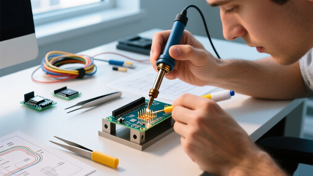
- The Tack: Set your station (e.g., Hakko FX-888D or Weller WE1010NA) to 360°C (680°F) if using 63/37 leaded eutectic solder. Apply a fresh, tinned coating to a 2.4mm chisel tip. Touch the tip to the pad and the pin simultaneously on the corner pin. Feed exactly 1-1.5mm of 0.031' (0.8mm) solder wire. Remove heat, hold the board still for 2 seconds until the joint solidifies.
- The Alignment Check: Inspect the tacked pin. Is the plastic spacer flush? Is the header perpendicular? If not, reheat the tacked joint and adjust. Once the corner is locked, the rest of the strip is mechanically secured.
- The Flux Sweep: Apply a generous line of no-clean liquid or tacky flux (such as Amtech NC-559-V2-TF or Chip Quik SMD291AX) across all remaining pins. As detailed in the Adafruit Guide to Excellent Soldering, external flux is the secret to rapid, bridge-free soldering. It lowers the surface tension, allowing the solder to wick instantly into the barrel.
- The Drag/Sweep: With a freshly cleaned and tinned tip, touch the pad and pin, feeding solder continuously while dragging the iron smoothly down the row. The flux will prevent bridging between the 0.1' pitch pins.
Workflow Metric: An unoptimized hobbyist takes roughly 12 minutes to solder the four header strips on an Arduino Nano (two 15-pin, two 8-pin) using the 'one-by-one' method. Using the Tack-and-Sweep method with external flux reduces this to under 4 minutes per board, with a 90% reduction in solder bridges.
Phase 3: Metallurgy and Consumables
Your choice of solder alloy directly impacts your workflow speed and joint reliability. In 2026, a 1lb spool of high-quality Kester 245 63/37 (Tin/Lead) rosin-core solder costs between $45 and $55. While expensive, it is an investment in workflow velocity.
- 63/37 Eutectic (Leaded): Melts at exactly 183°C. It transitions from liquid to solid instantly with no plastic state. This eliminates 'cold joints' caused by micro-movements during cooling. Highly recommended for rapid manual workflows.
- SAC305 (Lead-Free): Melts at ~217°C-220°C. Requires higher iron temperatures (380°C-400°C), which accelerates tip oxidation and necessitates more frequent tip changes. Only use this if your end-product requires RoHS compliance for commercial sale in the EU.
- Diameter Matters: Use 0.031' (0.8mm) or 0.020' (0.5mm) wire. Thicker wire (0.040'+) makes it difficult to control the exact volume of solder entering the PTH, leading to messy domed joints that violate IPC-A-610 visual inspection standards for through-hole components.
Phase 4: Trimming and Quality Control
Breakaway header pins often leave sharp, jagged plastic nubs when snapped to length. Do not use standard diagonal cutters to trim the plastic before soldering; this can crack the internal metal post, ruining the electrical connection.
The Optimized Trimming Workflow:
- Snap the pins to the required length (e.g., 15 pins for the Nano analog side) using your fingers or a specialized pin-snapping tool.
- Solder the pins to the board.
- Use flush cutters (like the Hakko CHP-170) to trim the metal overhang on the top side of the board, cutting flush with the top of the solder fillet. This prevents accidental short circuits when stacking shields or inserting the board into tight enclosures.
Visual Inspection Criteria
A perfect Arduino header pin joint should look like a smooth, shiny volcano (concave fillet). The solder should wet the entire circumference of the pin and flow out to the edge of the copper pad. If the joint looks dull, bulbous, or resembles a sphere sitting on top of the pad (convex), you have a cold joint or insufficient flux. Rework immediately by adding fresh flux and reheating with a clean tip.
Frequently Asked Questions (FAQ)
Why do my Arduino header pins keep bridging together?
Bridging on 0.1' pitch headers is almost always caused by a lack of external flux or a dirty soldering tip. The rosin core inside standard solder wire is rarely sufficient for dragging across multiple pins. Apply a high-quality no-clean tacky flux to the pins before soldering, and ensure your tip is wiped on a damp brass sponge between every few joints.
Can I use a hot air rework station to solder male header pins?
While technically possible, it is highly discouraged for workflow optimization. Hot air will melt the plastic spacer holding the pins together, causing the pins to shift, tilt, and ruin the PCB alignment. Stick to a temperature-controlled soldering iron with a chisel or bevel tip for through-hole headers.
How do I remove a misaligned header without lifting the Arduino pads?
Do not attempt to pry the header off while the solder is solid. Use a desoldering braid (copper wick) heavily saturated with flux to remove the bulk of the solder from the PTH barrels. Alternatively, if the header is cheap and sacrificial, use flush cutters to snip the plastic spacer, then pull out each individual metal pin one by one with tweezers while heating the pad. This drastically reduces the mechanical stress on the FR4 pad adhesion.