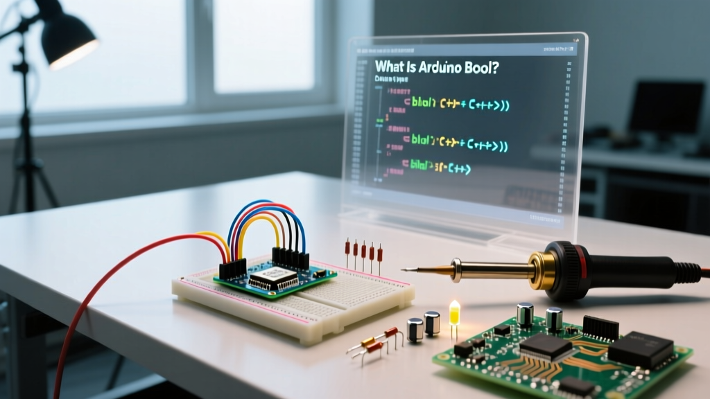

Defining the Core: What Is Arduino Bool?
When embedded engineers and hobbyists ask, 'what is arduino bool', they are typically navigating the intersection of standard C++ data types and the hardware constraints of microcontrollers. In the Arduino IDE, bool is a fundamental data type derived from standard C++ that represents a binary logical state: true or false. Under the hood, the GCC compiler used by the Arduino toolchain maps this logical state to a numerical value, where true evaluates to 1 and false evaluates to 0.
However, configuring your sketches to use boolean logic efficiently requires a deep understanding of memory allocation. Unlike high-level languages like Python or JavaScript that might dynamically pack boolean arrays into bits, C++ (and by extension, Arduino C++) allocates a full byte (8 bits) of memory for every single bool variable. This design choice prioritizes CPU addressing efficiency and memory alignment over raw storage density, which is generally optimal but can lead to severe SRAM exhaustion on constrained chips like the ATmega328P if not configured correctly.
The Anatomy of Boolean Memory Allocation
To truly understand what is arduino bool from a systems perspective, we must look at the sizeof() operator. According to the C++ Core Language Reference, the size of a bool is implementation-defined but is almost universally 1 byte on AVR and ARM Cortex-M architectures. This means that declaring an array of 1,000 booleans will consume exactly 1,000 bytes of SRAM.
On an Arduino Uno (ATmega328P), which possesses only 2,048 bytes of SRAM, a 1,000-element boolean array consumes nearly 50% of your total available memory, leaving insufficient room for the stack, heap, and serial buffers. Conversely, on an ESP32-S3 with 512KB of SRAM, this allocation is trivial. Therefore, your configuration strategy must adapt to the target MCU.
Historical Context: bool vs boolean
A common point of confusion in the Arduino Language Reference is the presence of the boolean keyword. Prior to Arduino IDE 1.0, boolean was a custom typedef mapped to uint8_t. Today, boolean is simply an alias for the standard C++ bool. For modern firmware development in 2026, it is highly recommended to configure your codebase using the standard bool keyword to ensure compatibility with external C++ libraries and MISRA-C++ compliance standards.
Data Type Configuration Matrix
Choosing the right logical data type is critical for MCU configuration. Below is a comparison matrix to help you decide between standard booleans and alternative integer types based on your project's memory and processing requirements.
| Data Type | Memory Footprint | Standard Compliance | Best Configuration Use Case |
|---|---|---|---|
bool |
1 Byte (8 bits) | Standard C++ | General logic flags, state machines, single-pin reads. |
boolean |
1 Byte (8 bits) | Arduino Legacy Alias | Backward compatibility with pre-2012 legacy sketches. |
uint8_t |
1 Byte (8 bits) | Standard C (stdint.h) | Bitwise packing (storing 8 boolean states in 1 byte). |
int |
2 Bytes (AVR) / 4 Bytes (ARM) | Standard C/C++ | Avoid for boolean logic; wastes SRAM and causes alignment padding issues. |
Advanced SRAM Configuration: Bitwise Boolean Packing
If your project requires tracking hundreds of binary states—such as a massive LED matrix, a complex button debounce matrix, or a multi-zone security alarm system—using standard bool arrays is a misconfiguration. Instead, you must configure your memory using bitwise operations on uint8_t or uint32_t variables.
By treating each bit within a byte as an independent boolean flag, you can reduce your SRAM footprint by exactly 87.5%. The AVR Libc FAQ heavily advocates for bitwise manipulation to preserve the heap and stack on 8-bit microcontrollers.
Step-by-Step Implementation: Bit-Masking Flags
Here is how you configure a 64-state boolean tracker using only 8 bytes of SRAM instead of 64 bytes:
// Configure an array of 8 bytes to hold 64 boolean states
uint8_t stateTracker[8] = {0};

void setFlag(uint8_t index, bool value) {
  uint8_t byteIndex = index / 8;
  uint8_t bitIndex = index % 8;

  if (value) {
    stateTracker[byteIndex] |= (1 << bitIndex);  // Set bit to 1 (true)
  } else {
    stateTracker[byteIndex] &= ~(1 << bitIndex); // Set bit to 0 (false)
  }
}

bool readFlag(uint8_t index) {
  uint8_t byteIndex = index / 8;
  uint8_t bitIndex = index % 8;
  return (stateTracker[byteIndex] >> bitIndex) & 1;
}
This configuration shifts the computational burden from memory bandwidth to the ALU (Arithmetic Logic Unit). On a 16MHz ATmega328P, bitwise shift operations execute in 1-2 clock cycles, making this optimization virtually cost-free in terms of execution time while saving massive amounts of SRAM.
Interrupt Configuration: The volatile Keyword
A critical failure mode when configuring boolean flags for Interrupt Service Routines (ISRs) is omitting the volatile qualifier. When you ask 'what is arduino bool' in the context of hardware interrupts, the answer must include memory volatility.
The GCC compiler utilizes aggressive optimization (typically the -Os flag in the Arduino IDE). If a standard bool is modified inside an ISR but read in the main loop(), the compiler may assume the variable never changes during the loop's execution and optimize the read operation out entirely, resulting in an infinite hang.
Configuring Volatile Booleans for ISRs
To configure the compiler to fetch the boolean state directly from SRAM on every clock cycle, you must declare it as volatile:
volatile bool interruptTriggered = false;

void setup() {
  Serial.begin(115200);
  // Configure hardware interrupt on Pin 2
  attachInterrupt(digitalPinToInterrupt(2), handleISR, RISING);
}

void loop() {
  if (interruptTriggered) {
    Serial.println('Event captured!');
    interruptTriggered = false; // Reset the flag
  }
}

void handleISR() {
  interruptTriggered = true; // Safely updates the volatile bool
}
Expert Warning: While volatile bool is safe for single-byte reads and writes on 8-bit AVR chips, it is not inherently atomic on 32-bit ARM Cortex-M MCUs (like the Arduino Zero or Portenta H7) if the variable were larger than a standard word size. For complex state machines in RTOS environments, configure your code to use std::atomic<bool> or hardware-specific mutexes.
IDE Configuration and Strict Compilation Warnings
To ensure your boolean logic is sound, you must configure the Arduino IDE to expose implicit conversion errors. By default, the Arduino IDE suppresses many standard C++ warnings. A common bug occurs when developers accidentally assign an integer to a bool (e.g., bool sensorState = analogRead(A0);), which forces the compiler to evaluate any non-zero analog reading as true.
Enabling Strict Boolean Typing
- Open the Arduino IDE and navigate to File > Preferences.
- Locate the 'Show verbose output during' section and check the compilation box.
- To enforce strict boolean configuration, navigate to your
platform.txtfile within the Arduino hardware package directory and append-Wconversion -Werror=return-typeto thecompiler.warning_flags.allparameter. - Alternatively, if you are using PlatformIO for professional MCU configuration, add
build_flags = -Wconversionto yourplatformio.inifile.
This configuration forces the compiler to throw an error if you attempt to implicitly cast a 10-bit ADC integer directly into a 1-bit logical boolean without explicit thresholding (e.g., bool sensorState = analogRead(A0) > 512;).
Summary of Best Practices
Understanding what is arduino bool extends far beyond simple true/false logic. It requires a holistic view of your microcontroller's architecture. Use standard bool for readability and state machines, employ uint8_t bitwise packing for high-density SRAM optimization, and rigorously apply the volatile keyword when bridging the gap between asynchronous hardware interrupts and your main execution loop. By configuring your data types intentionally, you ensure robust, crash-free firmware across both 8-bit and 32-bit platforms.