
The Illusion of Simplicity: HAL and the GPIO Protocol
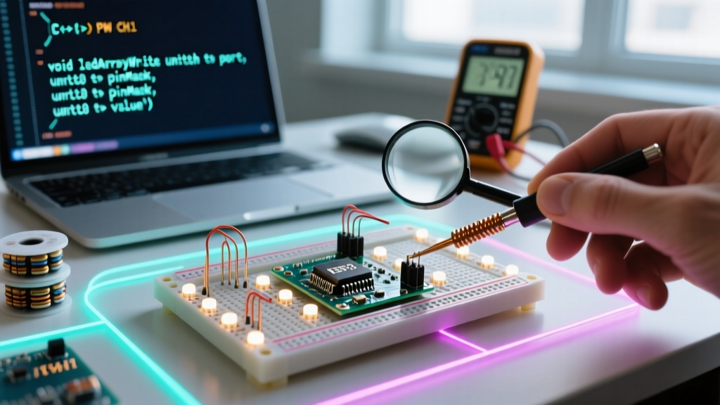
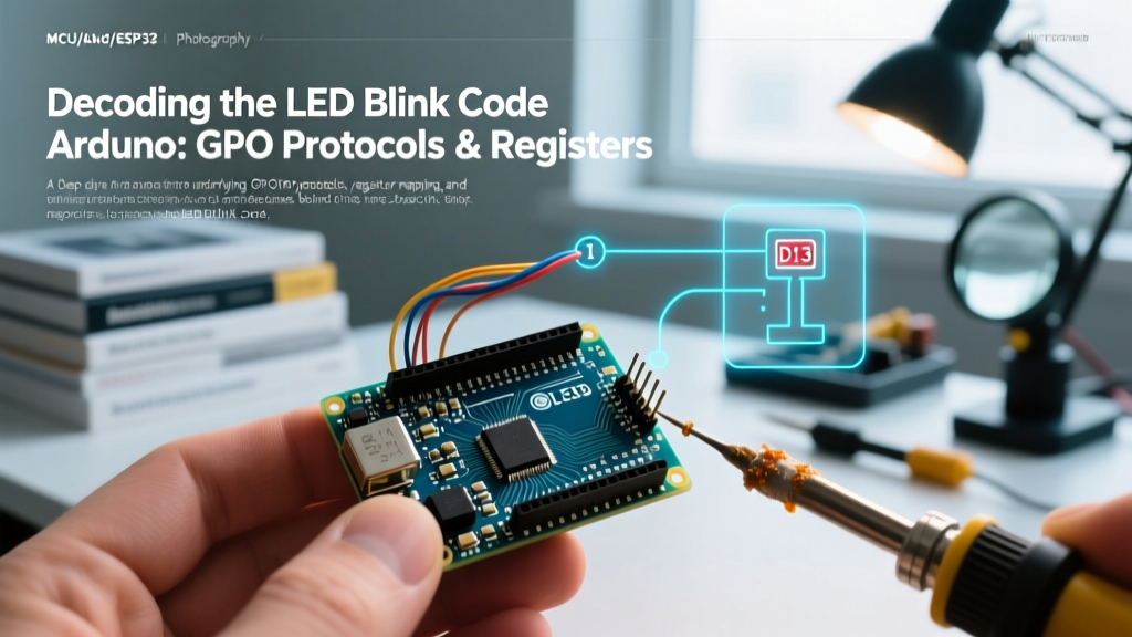
For millions of makers and engineers, writing the standard LED blink code Arduino is the definitive "Hello World" of embedded systems. You set a pin to OUTPUT, write it HIGH, delay, and write it LOW. But from a strict protocol and silicon-level perspective, toggling a General Purpose Input/Output (GPIO) pin is not a simple software command. It is a complex chain of hardware abstraction, memory-mapped register manipulation, and clock-cycle timing.
When you compile the standard blink sketch for an Arduino Uno R3 (ATmega328P) or an Uno R4 Minima (Renesas RA4M1), you are invoking the Hardware Abstraction Layer (HAL). The Arduino IDE masks the underlying GPIO communication protocol—the specific bitwise operations required to flip a transistor gate inside the microcontroller. According to the official Arduino digitalWrite Reference, the digitalWrite() function must first verify the pin number, disable any active PWM timers attached to that pin, look up the corresponding hardware port in a flash-resident array, and finally execute the bitwise operation. This abstraction guarantees cross-platform compatibility but introduces significant execution overhead.
Microcontroller Architecture Matrix: How Different MCUs Handle the Blink
The "blink protocol" changes drastically depending on the silicon architecture you are targeting in 2026. An 8-bit AVR microcontroller handles memory-mapped I/O very differently than a 32-bit ARM Cortex-M4 or an Xtensa-based Wi-Fi SoC. Below is a comparison of how the underlying GPIO registers are structured across three popular development boards.
| Microcontroller | Board Example | Architecture | GPIO Register Protocol | Execution Overhead (HAL) |
|---|---|---|---|---|
| ATmega328P | Arduino Uno R3 | 8-bit AVR | Direct Memory Mapped (e.g., PORTB, DDRB) |
~50-70 CPU cycles |
| Renesas RA4M1 | Arduino Uno R4 Minima | 32-bit ARM Cortex-M4 | Port Registers via PFS (Pin Function Select) | ~120+ CPU cycles |
| ESP32-C3 | ESP32-C3-DevKitM-1 | 32-bit RISC-V | GPIO Matrix & IO MUX Routing (GPIO_OUT_W1TS_REG) |
Highly variable (RTOS dependent) |
On the ESP32, for instance, the Espressif GPIO API documentation reveals that GPIO pins are not hardwired to specific internal peripherals. Instead, they use a flexible GPIO Matrix routing protocol. When you blink an LED on an ESP32, the signal must be routed through the IO MUX and the GPIO Matrix, adding layers of register configuration that the Arduino HAL silently manages for you.
Bypassing the Abstraction: Direct Port Manipulation
If you are building a high-speed data acquisition system or a custom bit-banged communication protocol (like a software-based SPI or WS2812B LED driver), the standard LED blink code Arduino is too slow. digitalWrite() takes roughly 3.2 microseconds on a 16MHz ATmega328P. Direct port manipulation reduces this to a single assembly instruction, taking just 62.5 nanoseconds (2 clock cycles).
The Bitwise Protocol
Instead of asking the HAL to find the pin, you write directly to the microcontroller's volatile memory registers. On the ATmega328P, the onboard LED is tied to PB5 (Port B, bit 5).
// Standard HAL Approach (Slow)
void setup() {
  pinMode(13, OUTPUT);
}
void loop() {
  digitalWrite(13, HIGH);
  delay(1);
  digitalWrite(13, LOW);
  delay(1);
}

// Direct Port Manipulation (Fast)
void setup() {
  DDRB |= (1 << DDB5); // Set PB5 as OUTPUT via Data Direction Register
}
void loop() {
  PORTB |= (1 << PORTB5);  // Set PB5 HIGH via Port Register
  _delay_us(50);           // Hardware-level AVR delay
  PORTB &= ~(1 << PORTB5); // Set PB5 LOW via bitwise AND-NOT
  _delay_us(50);
}
Expert Insight: While direct port manipulation yields massive speed gains, it destroys code portability. A sketch utilizing PORTB registers will compile but fail silently or cause erratic behavior if flashed to an Arduino Uno R4 or an ESP32, as their memory maps and register names are entirely different.
Timing Protocols: Software Blocking vs. Hardware Interrupts
The second half of the LED blink code Arduino is the timing mechanism. How the MCU tracks time is a protocol in itself, dictating whether your CPU is free to handle other tasks or locked in a blind loop.
1. The Busy-Wait Protocol (delay)
The delay(1000) function is a software blocking loop. It instructs the CPU to increment a volatile counter millions of times until the target millisecond count is reached. During this protocol, the MCU cannot read sensors, process serial data, or update displays. It is an anti-pattern in professional embedded firmware.
2. The Polling Protocol (millis)
Using millis() implements a non-blocking polling protocol. The MCU checks a background timer register on every loop iteration. While this frees the CPU to perform other tasks, it still requires the CPU to actively "ask" the timer if the time has elapsed, consuming bus bandwidth and power.
3. The Hardware Interrupt Protocol (Timer/Counters)
The most robust protocol for periodic tasks like blinking is utilizing the MCU's hardware Timer/Counter peripherals. By configuring a hardware timer to overflow at a specific interval (e.g., 500ms) and triggering an Interrupt Service Routine (ISR), the CPU remains entirely asleep or focused on primary tasks. The hardware peripheral handles the blink protocol autonomously.
Electrical Protocols: Sinking, Sourcing, and Current Limits
Software protocols mean nothing if the electrical protocol violates the silicon's physical limits. The Microchip ATmega328P datasheet specifies strict DC current limitations that every engineer must respect when wiring an LED.
- Current Sourcing (Pin provides current): The GPIO pin outputs VCC (usually 5V or 3.3V) through the LED to ground.
- Current Sinking (Pin absorbs current): The LED is tied to VCC, and the GPIO pin pulls the signal to ground. Many MCUs can sink slightly more current safely than they can source, though the ATmega328P is symmetrical at 20mA per pin.
- The Absolute Maximum Trap: The absolute maximum rating per I/O pin is 40mA. Exceeding this will degrade the internal output driver transistors, leading to permanent voltage droop or silicon death. Furthermore, the total current through the VCC/GND rails must not exceed 200mA across all pins combined.
Resistor Calculation Protocol: Never wire an LED directly to a GPIO pin. You must use a current-limiting resistor. For a standard red LED (Forward Voltage $V_f = 2.1V$, Desired Current $I_f = 15mA$) on a 5V Arduino Uno:
$R = (V_{cc} - V_f) / I_f$
$R = (5.0V - 2.1V) / 0.015A = 193\Omega$
Select the next highest standard E12 resistor value: 220Ω.
Edge Case Troubleshooting Matrix
When your LED blink code Arduino fails to behave as expected, the issue is rarely the C++ syntax. It is usually a collision between software states and electrical realities. Use this matrix to diagnose anomalous blink behavior.
| Symptom | Underlying Protocol Conflict | Resolution Strategy |
|---|---|---|
| LED glows dimly but never fully turns off. | PWM Timer Conflict. The pin was previously initialized with analogWrite() and the hardware timer is still active in the background. |
Explicitly call digitalWrite(pin, LOW) before pinMode(pin, OUTPUT) to ensure the HAL disconnects the timer multiplexer. |
| Blink rate is erratic or halves in speed. | Interrupt Starvation. A heavy ISR (like a software serial read) is blocking the millis() timer0 overflow interrupt from updating. |
Keep ISRs under 10 microseconds. Move heavy processing to the main loop() using state-machine flags. |
| MCU resets randomly when LED turns on. | Brown-out Detection (BOD) triggered by voltage sag. The LED is drawing too much current, pulling the VCC rail below the BOD threshold (typically 2.7V or 4.3V). | Increase the current-limiting resistor value to lower $I_f$, or drive the LED via an external N-channel MOSFET (e.g., 2N7000) to isolate the MCU's power rail. |
| Code compiles, pin reads HIGH on multimeter, but LED is dark. | Polarity / Sinking mismatch. The LED is wired in reverse, or the GPIO is configured as INPUT_PULLUP instead of OUTPUT, providing only ~30µA of current. |
Verify anode/cathode orientation. Ensure pinMode() is strictly set to OUTPUT. Check for cold solder joints on the ground return path. |
Conclusion: Respecting the Silicon
The standard LED blink code Arduino is a brilliant educational tool, but it is merely the surface layer of embedded systems engineering. By understanding the GPIO communication protocols, the overhead of the Hardware Abstraction Layer, and the strict electrical limits of the silicon, you transition from a script-writer to a firmware engineer. Whether you are utilizing the flexible GPIO matrix of an ESP32-C3 or manipulating the raw PORTB registers of an ATmega328P, mastering the underlying protocols ensures your designs are robust, power-efficient, and ready for production-level deployment.