
The Anatomy of Wire Library Arduino I2C Failures
The I2C (Inter-Integrated Circuit) protocol is the backbone of Arduino sensor integration, but it is notoriously fragile when hardware and software configurations misalign. When working with the Wire library Arduino developers rely on, the underlying AVR or ESP32 TWI (Two-Wire Interface) hardware state machine can easily enter an unrecoverable lockup. Unlike SPI or UART, I2C requires precise pull-up resistances, strict address formatting, and careful bus capacitance management. This error fix guide dissects the most common Wire library failures—from infinite sketch freezes to silent data truncation—and provides exact hardware and software solutions to restore reliable communication.
Error 1: The Infinite Hang (Wire.endTransmission Freezing)
The most dreaded issue when using the Wire library is a sketch that freezes indefinitely at Wire.endTransmission() or Wire.requestFrom(). This occurs when the I2C master (your Arduino) waits for a clock pulse or an acknowledgment (ACK) that never arrives.
Root Causes
- Missing Pull-Up Resistors: I2C lines (SDA and SCL) are open-drain. Without pull-up resistors to VCC, the lines float, and the master cannot detect a high state.
- Slave Bus Lockup: If a slave device (like an MPU6050 or BME280) is interrupted mid-transmission via a hardware reset, it may continue holding the SDA line LOW, waiting for clock pulses that the master has stopped sending.
- Capacitive Overload: Long wires increase bus capacitance, causing signal rise times to exceed the I2C specification thresholds.
The Software Fix: Implementing Timeouts
Modern AVR cores for Arduino include a timeout feature to prevent infinite blocking. By default, it is disabled. You can enable it by adding a timeout threshold in microseconds. If the transmission exceeds this time, the Wire library aborts and returns an error code instead of hanging.
void setup() {
  Wire.begin();
  // Set timeout to 25,000 microseconds (25ms) and reset the bus on timeout
  Wire.setWireTimeout(25000, true);
}
The Hardware Fix: Bus Recovery and Pull-Ups
According to the NXP I2C-bus specification (UM10204), the maximum bus capacitance is 400pF. For standard 100kHz I2C, use 4.7kΩ pull-up resistors on both SDA and SCL to VCC. For Fast Mode (400kHz), drop to 2.2kΩ to overcome capacitance and sharpen the signal rise time. If a slave locks the bus, implement a hardware bus recovery circuit using a MOSFET to forcibly toggle the SCL line until the slave releases SDA.
Error 2: NACK (Not Acknowledged) on Address or Data
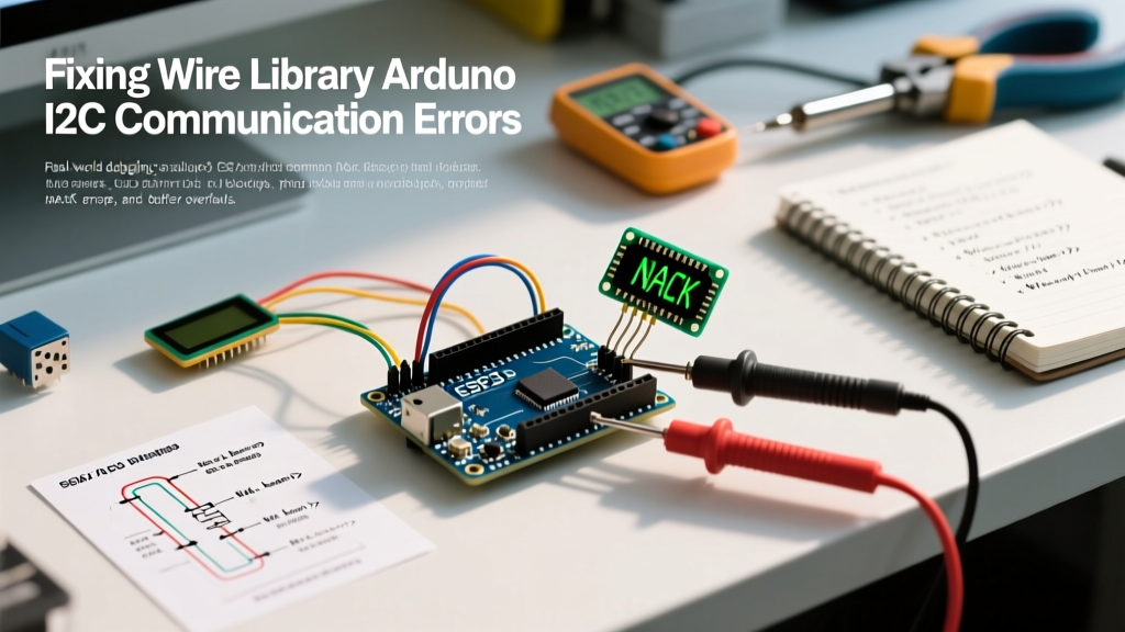
When Wire.endTransmission() returns a 2 or 3, the slave is actively rejecting the master. A return code of 2 means the address was NACKed; a 3 means the data byte was NACKed.
Address Shifting Confusion (7-bit vs. 8-bit)
Many sensor datasheets list 8-bit I2C addresses (which include the Read/Write bit), while the Arduino Wire library strictly requires 7-bit addresses. For example, the DS3231 RTC datasheet might list the write address as 0xD0. If you pass 0xD0 to Wire.beginTransmission(), you will get a NACK. You must shift the address right by one bit: 0xD0 >> 1 equals 0x68.
Address Pin Misconfiguration
Modules like the PCF8574 I/O expander or ADS1115 ADC have hardware pins (A0, A1, A2) that alter the I2C address. If these pins are left floating, environmental noise can cause the slave to dynamically change its address mid-operation. Always tie address pins explicitly to GND or VCC using 10kΩ resistors or direct jumper wires.
Error 3: Silent Data Truncation (The 32-Byte Buffer Limit)
If you are requesting a large block of data (e.g., reading a 64-byte FIFO buffer from an accelerometer) and only receiving the first chunk, you have hit the hardware buffer limit.
Understanding TWI_BUFFER_LENGTH
On standard 8-bit AVR boards (Arduino Uno, Nano, Mega), the Wire library allocates a static 32-byte buffer defined by TWI_BUFFER_LENGTH in the Wire.h source code. If you call Wire.requestFrom(address, 64), the library will silently truncate the request to 32 bytes. Conversely, ESP32 and SAMD21 architectures feature 128-byte or 256-byte buffers.
Solutions for Buffer Overflow
- Chunking Data: Write a loop to request data in 16-byte or 32-byte increments. This is the safest method as it requires no core modifications.
- Modifying the Core (Advanced): Navigate to your Arduino IDE hardware folder, locate
Wire.hfor your specific AVR core, and change#define TWI_BUFFER_LENGTH 32to64or128. Note that this consumes precious SRAM, which is limited to 2KB on the ATmega328P.
Error 4: Logic Level Violations (3.3V vs 5V)
Connecting a 5V Arduino Uno directly to a 3.3V sensor (like the BME280 or VL53L0X) without level shifting is a primary cause of degraded I2C performance and eventual silicon death. The Wire library will output 5V on the SDA/SCL lines, violating the absolute maximum ratings of 3.3V components.
While some 3.3V sensors have 5V-tolerant I2C pins, relying on this is poor engineering practice. Use a bidirectional logic level shifter based on the BSS138 MOSFET topology. Avoid the TXB0108 level shifter for I2C; its internal auto-direction sensing circuitry frequently conflicts with I2C clock stretching and open-drain requirements, leading to bus lockups.
Diagnostic Matrix: Wire.endTransmission() Return Codes
Always capture the integer returned by Wire.endTransmission() to programmatically handle I2C faults. Below is the definitive error matrix for the Wire library:
| Return Code | Meaning | Primary Culprit | Recommended Action |
|---|---|---|---|
| 0 | Success | None | Proceed with data parsing. |
| 1 | Data too long for buffer | Exceeded TWI_BUFFER_LENGTH | Reduce payload size or chunk requests. |
| 2 | NACK on Address | Wrong address, missing pull-ups, or dead slave | Run I2C Scanner; check 7-bit shifting and wiring. |
| 3 | NACK on Data | Slave rejected payload or register map error | Verify register addresses and write permissions. |
| 4 | Other Error | Bus collision or internal TWI state machine fault | Reset the I2C peripheral or power cycle the bus. |
| 5 | Timeout | SDA/SCL held low, clock stretch failure | Check for slave lockup; verify pull-up resistor values. |
Advanced Hardware Debugging with an Oscilloscope
When software diagnostics fail, you must inspect the physical layer. Connect a digital storage oscilloscope or a logic analyzer to the SDA and SCL lines.
- Inspect Rise Times: According to SparkFun's I2C tutorial and NXP standards, the rise time for Standard Mode (100kHz) must not exceed 1000ns, and Fast Mode (400kHz) must not exceed 300ns. If your oscilloscope shows a slow, curved RC charging slope instead of a sharp square wave, your bus capacitance is too high. Lower your pull-up resistor values.
- Clock Stretching: Some sensors hold SCL LOW to force the master to wait while they process data. If the master does not support clock stretching (or if the Wire library timeout is too aggressive), the transmission will abort. Ensure your logic analyzer triggers on the SCL line to verify if the slave is actively stretching the clock.
Expert Tip: Never use the internal pull-up resistors of the ATmega328P (
INPUT_PULLUP) for I2C. They are typically 20kΩ to 50kΩ, which is far too weak to pull the bus high quickly enough for reliable communication, resulting in severe data corruption at speeds above 100kHz.
Summary Checklist for I2C Stability
Before blaming the sensor or the Wire library code, run through this physical and logical checklist:
- Verify 4.7kΩ external pull-up resistors are present on both SDA and SCL.
- Confirm the I2C address is in 7-bit format and matches the hardware pin configuration.
- Implement
Wire.setWireTimeout()to prevent sketch lockups. - Ensure voltage levels match, utilizing BSS138 level shifters for mixed 5V/3.3V buses.
- Keep I2C trace lengths under 30cm to maintain bus capacitance below 400pF.
By systematically addressing the physical layer constraints and leveraging the Wire library's built-in timeout and error-reporting features, you can transform I2C from a frustrating bottleneck into a robust, reliable communication bus for your embedded projects.