
The Anatomy of the Arduino Wire Library
The Wire.h library is the backbone of I2C (Inter-Integrated Circuit) communication in the Arduino ecosystem. Whether you are polling a BME280 environmental sensor, driving an SSD1306 OLED display, or establishing a multi-node telemetry network, the Wire library abstracts the complex TWI (Two-Wire Interface) hardware registers into accessible C++ functions. However, treating it as a simple plug-and-play abstraction often leads to bus lockups, silent data corruption, and NACK (Not Acknowledged) errors in production environments.
In this comprehensive walkthrough, we will dissect the Arduino Wire library from a master-slave perspective. We will cover the physical layer requirements, dissect the C++ implementation, and troubleshoot the edge cases that separate hobbyist prototypes from robust 2026 industrial IoT deployments.
Hardware Prerequisites: Pull-Up Resistor Math
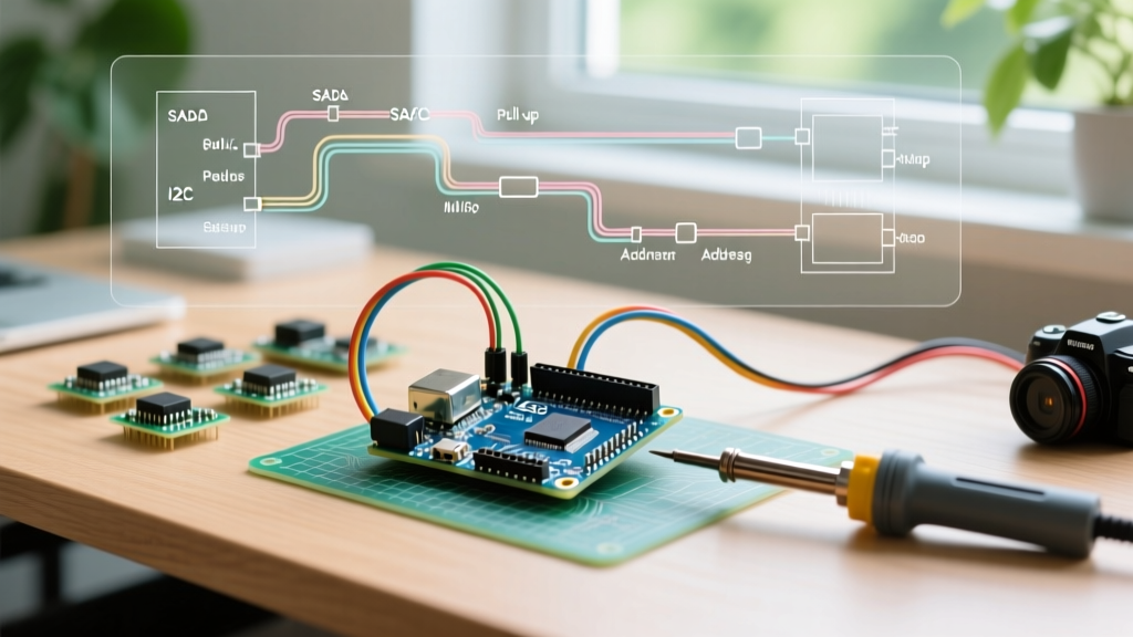
Before writing a single line of code, you must validate the physical bus. I2C is an open-drain protocol; the microcontroller can only pull the SDA and SCL lines LOW. It relies on external pull-up resistors to bring the lines HIGH. The NXP I2C-bus Specification (UM10204) strictly defines the electrical characteristics, yet missing or incorrectly sized pull-ups remain the number one cause of Wire library failures.
Calculating the Correct Pull-Up Value
The resistor value is dictated by the bus capacitance (trace length, number of devices) and the desired clock speed. The maximum allowed bus capacitance is 400pF.
- Standard Mode (100kHz): 4.7kΩ resistors are the standard baseline for short runs (<30cm) with 1-3 devices.
- Fast Mode (400kHz): The rise time must be much faster. Drop to 2.2kΩ or even 1kΩ if your bus capacitance approaches 200pF.
Pro-Tip for ESP32 Users: The ESP32's internal pull-ups are roughly 45kΩ—far too weak for reliable I2C. Always disable internal pull-ups in your code and rely on external 4.7kΩ or 2.2kΩ physical resistors tied to 3.3V.
Master Transmitter Walkthrough
Let us configure an Arduino Uno R4 Minima as the Master, transmitting telemetry data to a slave node. The R4's Renesas RA4M1 processor handles I2C via DMA, but the Wire API remains identical to the classic ATmega328P for backward compatibility.
#include <Wire.h>

#define SLAVE_ADDR 0x18

void setup() {
  Serial.begin(115200);
  // Initialize I2C as Master, set SDA to pin A4, SCL to A5 (default on AVR)
  Wire.begin();
  // For 400kHz Fast Mode:
  Wire.setClock(400000);
}

void loop() {
  Wire.beginTransmission(SLAVE_ADDR);

  // Payload: Command byte + 2 data bytes
  Wire.write(0x01);       // Command: Update Threshold
  Wire.write(highByte(512)); // MSB
  Wire.write(lowByte(512));  // LSB

  uint8_t error = Wire.endTransmission();

  if (error == 0) {
    Serial.println("Success: Slave ACKed all bytes.");
  } else {
    Serial.print("I2C Error Code: ");
    Serial.println(error);
  }

  delay(1000);
}
Decoding endTransmission() Return Values
The most critical, yet frequently ignored, aspect of the Arduino Wire Language Reference is the return value of Wire.endTransmission(). It does not simply return a boolean. It returns an integer status code that tells you exactly where the bus failed.
| Code | Status | Root Cause & Action |
|---|---|---|
| 0 | Success | All bytes transmitted and ACKed by slave. |
| 1 | Buffer Overflow | Data exceeds the internal TX buffer. Chunk your payload. |
| 2 | NACK (Address) | Slave not found. Check wiring, pull-ups, and I2C address. |
| 3 | NACK (Data) | Slave rejected a data byte. Usually a firmware bug on the slave. |
| 4 | Other Error | Bus collision or hardware fault. Reset the TWI peripheral. |
| 5 | Timeout | SCL held LOW by slave (Clock Stretching) or bus lockup. |
Slave Receiver Walkthrough
Now, we program the receiving node. The slave operates on an event-driven model using hardware interrupts. The Wire.onReceive() callback triggers the moment the master issues a STOP condition after a write operation.
#include <Wire.h>

#define SLAVE_ADDR 0x18

void setup() {
  Wire.begin(SLAVE_ADDR); // Join bus as Slave
  Wire.onReceive(receiveEvent);
  Wire.onRequest(requestEvent);
}

void loop() {
  // Main loop remains free for other tasks
}

void receiveEvent(int numBytes) {
  if (numBytes >= 3) {
    uint8_t cmd = Wire.read();
    uint8_t msb = Wire.read();
    uint8_t lsb = Wire.read();
    int payload = (msb << 8) | lsb;

    if (cmd == 0x01) {
      // Process threshold update
    }
  }
}

void requestEvent() {
  // Master is requesting data via Wire.requestFrom()
  Wire.write(0xFF); // Send status byte back
}
Overcoming the 32-Byte Buffer Bottleneck
A classic trap for developers migrating from basic sensors to complex OLED displays or EEPROMs is the hardware buffer limit. On legacy AVR boards (Uno R3, Nano, Mega), the BUFFER_LENGTH macro in Wire.h is hardcoded to 32 bytes. If you attempt to Wire.write() 64 bytes in a single transmission, the library will truncate the data or throw Error Code 1.
The Solution: Payload Chunking
You must break large transfers into 32-byte (or smaller) chunks. Modern boards like the ESP32 or Arduino Uno R4 feature 128-byte or 256-byte buffers, but writing cross-compatible code requires assuming the lowest common denominator.
void sendLargePayload(uint8_t *data, size_t length) {
  size_t chunkSize = 32;
  for (size_t i = 0; i < length; i += chunkSize) {
    Wire.beginTransmission(SLAVE_ADDR);
    size_t bytesToSend = min(chunkSize, length - i);
    Wire.write(data + i, bytesToSend);
    Wire.endTransmission();
    delayMicroseconds(100); // Brief pause for slave processing
  }
}
Real-World Failure Modes & Debugging
When the Wire library fails silently or hangs your microcontroller, software debugging is insufficient. You must inspect the physical layer. According to Adafruit's I2C addressing guidelines, address conflicts and bus noise are rampant in multi-sensor arrays.
1. Clock Stretching Timeouts
Some sensors (like the SHT31) hold the SCL line LOW to buy processing time. If the master's timeout threshold is too aggressive, it will abandon the transaction. On AVR, you can adjust the timeout using Wire.setWireTimeout(50000, true); (setting a 50ms timeout and enabling auto-reset).
2. Bus Lockups (SDA Stuck LOW)
If a master resets mid-transaction while a slave is outputting a '0' bit, the slave will hold SDA LOW indefinitely, locking the bus.
Recovery Protocol: Do not rely on Wire.begin() to fix this. Write a software recovery routine that manually toggles the SCL pin as a GPIO 9 times, followed by a STOP condition, before re-initializing the Wire library.
3. Logic Analyzer Verification
Stop guessing. Invest in a logic analyzer. While a Saleae Logic Pro 8 retails around $149, generic 24MHz 8-channel clones ($15-$25) running Sigrok/PulseView are perfectly adequate for decoding 400kHz I2C frames. Look for missing ACK bits (the 9th clock cycle where SDA should be pulled LOW by the receiver). If SDA stays HIGH on the 9th clock, you have a NACK.
Summary
The Arduino Wire library is a powerful abstraction, but it does not protect you from the laws of physics or hardware limitations. By calculating proper pull-up resistors, rigorously checking endTransmission() return codes, chunking large payloads to respect buffer limits, and utilizing logic analyzers for physical debugging, you can build I2C networks that operate flawlessly in the field.