
Mastering the Arduino to Bluetooth Module HC-05 Connection
As of 2026, while Bluetooth Low Energy (BLE) and integrated Wi-Fi/BLE SoCs like the ESP32 dominate new IoT deployments, the classic HC-05 remains the undisputed workhorse for hobbyists, RC vehicles, and legacy serial terminal applications. Connecting an Arduino to Bluetooth module hardware is straightforward, but achieving a stable, noise-free serial link requires a firm grasp of logic level shifting, baud rate synchronization, and the SoftwareSerial library.
In this comprehensive code tutorial and walkthrough, we will build a robust smartphone-controlled serial link. We will cover the exact wiring topology required to prevent silicon damage, walk through the AT command configuration, and write a production-ready Arduino sketch that bridges hardware serial debugging with Bluetooth data streams.
Hardware Selection Matrix: HC-05 vs. Modern Alternatives
Before writing code, it is critical to select the right module for your bandwidth and power constraints. Below is a comparison of the most common serial Bluetooth modules available to makers.
| Module | Protocol | Default Baud | Avg. Cost (2026) | Best Use Case |
|---|---|---|---|---|
| HC-05 | Bluetooth 2.0 EDR (SPP) | 9600 bps | $5.00 - $8.00 | RC cars, serial terminal bridging, AT command config |
| HC-06 | Bluetooth 2.0 EDR (SPP) | 9600 bps | $4.00 - $6.00 | Slave-only applications (no master pairing required) |
| HM-10 | Bluetooth 4.0 BLE | 9600 bps | $4.50 - $7.00 | Battery-powered sensors, iOS compatibility |
| ESP32 (Built-in) | BT 4.2 / BLE 4.2 | N/A (Native) | $6.00 - $10.00 | Complex IoT, web servers, multi-core processing |
For this walkthrough, we are using the HC-05 due to its dual Master/Slave capabilities and widespread support in generic Android serial terminal apps.
Wiring Topology & The 3.3V Logic Imperative
The most common point of failure when wiring an Arduino to Bluetooth module setups is ignoring logic voltage thresholds. The Arduino Uno (ATmega328P) operates at 5V logic. The HC-05 operates at 3.3V logic. While the HC-05's TX pin outputs 3.3V (which the Uno safely reads as a HIGH signal), the Uno's TX pin outputs 5V, which will slowly degrade the HC-05's RX pin and cause data corruption.
The Voltage Divider Solution
You must step down the 5V TX signal from the Arduino to a safe 3.3V for the HC-05 RX pin using a simple resistor voltage divider.
- R1 (1kΩ Resistor): Connect between Arduino Pin 11 (TX) and HC-05 RXD.
- R2 (2kΩ Resistor): Connect between HC-05 RXD and GND.
Engineering Note: Using the formula Vout = Vin * (R2 / (R1 + R2)), we get 5V * (2000 / 3000) = 3.33V. This is perfectly within the HC-05's 3.3V tolerance. Do not skip this step if you want long-term reliability.
Complete Pinout Map
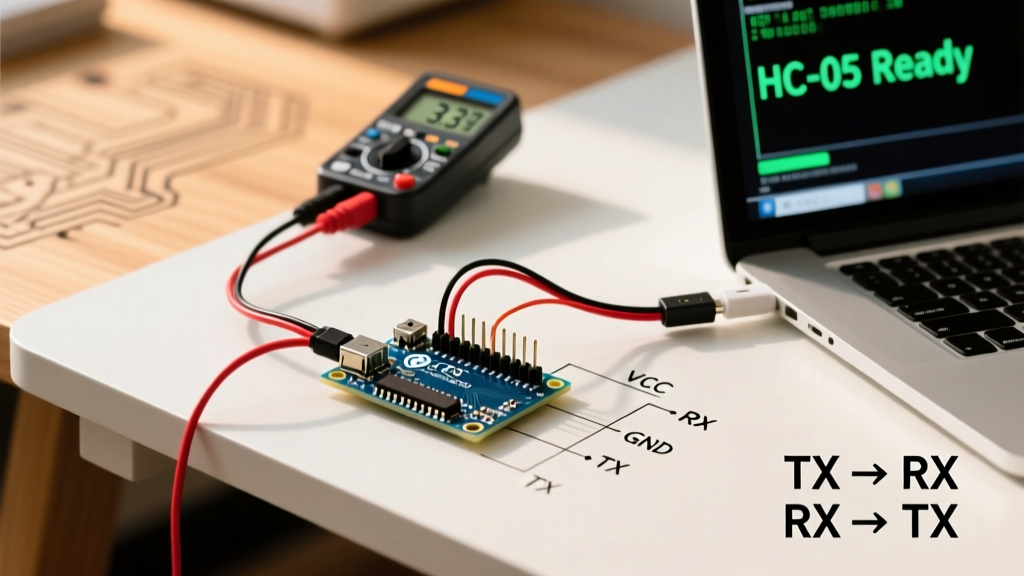
- VCC: Arduino 5V pin (The HC-05 has an onboard 3.3V regulator. Do not use the Arduino 3.3V pin, as it cannot supply the 50mA+ peak current required during pairing).
- GND: Arduino GND.
- TXD: Arduino Pin 10 (SoftwareSerial RX).
- RXD: Voltage Divider output from Arduino Pin 11 (SoftwareSerial TX).
Step 1: AT Command Configuration
Out of the box, the HC-05 defaults to 9600 bps in data mode, but its AT command mode runs at 38400 bps. To change the device name or pairing PIN, you must enter AT mode.
- Disconnect power from the HC-05.
- Press and hold the tiny pushbutton on the HC-05 breakout board.
- Apply power (plug in the Arduino USB) while holding the button.
- Release the button. The onboard LED should now blink slowly (once every 2 seconds), indicating AT mode.
- Open the Arduino IDE Serial Monitor, set the baud rate to 38400, and select Both NL & CR.
Send the following commands to configure your module:
AT(Should returnOK)AT+NAME=FluxBot01(Changes broadcast name)AT+PSWD=4321(Changes default PIN from 1234 to 4321)AT+UART=9600,0,0(Locks data mode to 9600 baud, 1 stop bit, no parity)
Step 2: The Arduino Sketch (Code Walkthrough)
Now we write the firmware. We will use the Arduino SoftwareSerial library to create a secondary serial port on pins 10 and 11. This leaves the hardware serial port (Pins 0 and 1) free for debugging via the USB Serial Monitor.
According to the official Arduino Software Serial Guide, not all pins support RX interrupts. On the Uno, pins 10 and 11 are fully supported for RX and TX operations.
#include <SoftwareSerial.h>

// Define SoftwareSerial pins: RX = 10, TX = 11
SoftwareSerial BTSerial(10, 11);

const int RELAY_PIN = 8;
char incomingByte;

void setup() {
  // Initialize hardware serial for USB debugging at 9600 baud
  Serial.begin(9600);

  // Initialize software serial for HC-05 communication at 9600 baud
  BTSerial.begin(9600);

  pinMode(RELAY_PIN, OUTPUT);
  digitalWrite(RELAY_PIN, LOW);

  Serial.println(F("System Ready. Waiting for Bluetooth commands..."));
}

void loop() {
  // Bridge Bluetooth to USB Serial (Read from BT, print to Monitor)
  if (BTSerial.available()) {
    incomingByte = BTSerial.read();
    Serial.print(F("Received via BT: "));
    Serial.println(incomingByte);

    processCommand(incomingByte);
  }

  // Bridge USB Serial to Bluetooth (Read from Monitor, send to BT)
  if (Serial.available()) {
    incomingByte = Serial.read();
    BTSerial.write(incomingByte);
  }
}

void processCommand(char cmd) {
  switch(cmd) {
    case '1':
      digitalWrite(RELAY_PIN, HIGH);
      BTSerial.println(F("RELAY_ON"));
      break;
    case '0':
      digitalWrite(RELAY_PIN, LOW);
      BTSerial.println(F("RELAY_OFF"));
      break;
    case '?':
      BTSerial.println(F("STATUS: OK"));
      break;
    default:
      BTSerial.println(F("ERR: UNKNOWN_CMD"));
      break;
  }
}
Code Architecture Breakdown
- Non-Blocking Bridge: The
loop()function checks bothBTSerial.available()andSerial.available()without usingdelay(). This ensures zero latency when toggling the relay. - Flash String Helper: Notice the use of the
F()macro around strings likeF("RELAY_ON"). This forces the compiler to store strings in Flash memory rather than SRAM, preventing memory overflow on the ATmega328P's limited 2KB RAM. - Switch-Case Parser: Instead of using heavy
Stringobjects which cause heap fragmentation, we parse singlecharbytes. This is a critical optimization for 8-bit microcontrollers handling continuous serial streams.
Troubleshooting Edge Cases & Failure Modes
Even with perfect code, RF environments and power anomalies can disrupt your Arduino to Bluetooth module link. Use this diagnostic matrix to resolve common issues.
| Symptom | Root Cause | Engineering Fix |
|---|---|---|
Serial Monitor prints junk characters (⸮⸮⸮) |
Baud rate mismatch between HC-05 and BTSerial.begin(). |
Verify HC-05 AT mode UART settings. Ensure BTSerial.begin(9600) matches the module's data mode baud rate. |
| App connects but drops instantly | Voltage brownout on the 5V rail during RF transmission spikes. | Power the Arduino via the barrel jack (7-12V) instead of a weak USB port. Add a 100µF decoupling capacitor across HC-05 VCC/GND. |
| Module not discoverable on phone | Module is stuck in Master mode or AT mode. | Re-enter AT mode and send AT+ROLE=0 to force Slave mode. Cycle power to exit AT mode (LED should blink rapidly). |
| Data loss at high speeds | SoftwareSerial buffer overflow (64-byte limit). |
Reduce baud rate to 9600, or migrate to an Arduino Mega2560 which features 4 hardware UARTs. |
Final Thoughts on Serial Bluetooth
Bridging an Arduino to Bluetooth module hardware like the HC-05 is a foundational skill in embedded systems. While the Bluetooth SIG continues to push mesh networking and LE Audio in their latest core specifications, the Serial Port Profile (SPP) utilized by the HC-05 remains unmatched for raw simplicity in robotics and telemetry. By respecting logic level thresholds, managing SRAM efficiently with the F() macro, and utilizing non-blocking serial bridges, your projects will achieve industrial-grade reliability in a hobbyist form factor.