
Understanding the Magic of Pulse Width Modulation
Microcontrollers like the Arduino Uno are fundamentally digital devices. Their GPIO pins can only output two states: HIGH (typically 5V or 3.3V) and LOW (0V). But what if you need 2.5V to dim an LED or run a DC motor at half speed? You cannot output a true analog voltage directly from a standard digital pin. This is where Pulse Width Modulation (PWM) becomes essential.
PWM simulates an analog voltage by rapidly toggling a digital pin between HIGH and LOW. By adjusting the ratio of the 'ON' time to the 'OFF' time—known as the duty cycle—you can control the average power delivered to a component. According to SparkFun's educational guides, a 50% duty cycle on a 5V pin delivers an average of 2.5V, while a 20% duty cycle delivers 1V.
💡 The Water Hose Analogy: Imagine turning a garden hose on and off every second. If you leave it on for half a second and off for half a second, the bucket fills at exactly half the maximum rate. The water is either fully ON or fully OFF, but the average flow is 50%. PWM works exactly like this, but it switches thousands of times per second so the human eye (and most electronics) only perceives the average.PWM-Capable Pins Across Popular Arduino Boards
Not all pins on an Arduino can output a PWM signal. You must use pins specifically tied to the microcontroller's internal hardware timers. On most boards, these are marked with a tilde (~) symbol.
| Arduino Board | PWM-Capable Pins | Default Frequency |
|---|---|---|
| Uno R3 (ATmega328P) | 3, 5, 6, 9, 10, 11 | ~490 Hz (Pins 5, 6 are ~980 Hz) |
| Nano (ATmega328P) | 3, 5, 6, 9, 10, 11 | ~490 Hz (Pins 5, 6 are ~980 Hz) |
| Mega 2560 | 2-13, 44-46 | ~490 Hz (Pins 4, 13 are ~980 Hz) |
| Uno R4 Minima (Renesas RA4M1) | 3, 5, 6, 9, 10, 11 (Plus true DAC on A0) | Configurable (Default ~490 Hz) |
Expert Note: Why are pins 5 and 6 running at 980 Hz on the classic Uno R3? They share Timer0 with the millis() and delay() functions. Altering the frequency on these specific pins will break your timing functions. Always use pins 9, 10, or 11 if you plan to modify timer registers.
Writing Your First Arduino Pulse Width Modulation Code
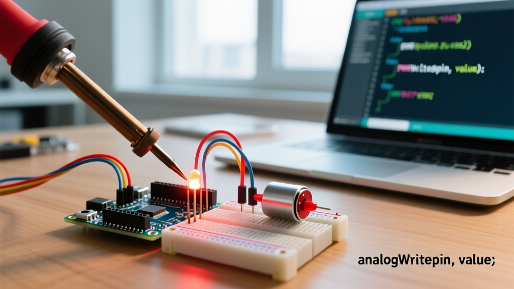
The Arduino IDE abstracts the complex timer register configurations into a single, beginner-friendly function: analogWrite(). As detailed in the official Arduino language reference, this function accepts two arguments: the pin number and the duty cycle value.
The duty cycle value ranges from 0 (always OFF) to 255 (always ON). Therefore, a value of 127 represents roughly a 50% duty cycle.
// Basic PWM Syntax
int pwmPin = 9;

void setup() {
  // No need to set pinMode to OUTPUT for analogWrite, but it's good practice
  pinMode(pwmPin, OUTPUT);
}

void loop() {
  analogWrite(pwmPin, 64);  // ~25% duty cycle (Dim LED)
  delay(2000);
  analogWrite(pwmPin, 191); // ~75% duty cycle (Bright LED)
  delay(2000);
}
Project 1: The 'Breathing' LED Circuit
Let's apply this to a real circuit. A smooth 'breathing' effect requires incrementing and decrementing the PWM value inside a loop.
Hardware Requirements & Wiring
- Microcontroller: Arduino Uno R3 or R4 Minima (~$27 retail).
- LED: Standard 5mm Diffused LED.
- Resistor: 220Ω for Red/Green/Yellow; 330Ω for Blue/White (to limit current to a safe ~15-20mA).
- Jumper Wires & Breadboard.
Wiring: Connect Pin 9 to the anode (long leg) of the LED. Connect the cathode (short leg) to one end of the 220Ω resistor. Connect the other end of the resistor to the Arduino GND pin.
The Breathing Code
int ledPin = 9;
int brightness = 0;
int fadeAmount = 5;

void setup() {
  pinMode(ledPin, OUTPUT);
}

void loop() {
  analogWrite(ledPin, brightness);
  brightness = brightness + fadeAmount;

  // Reverse the fade direction at the limits
  if (brightness <= 0 || brightness >= 255) {
    fadeAmount = -fadeAmount;
  }

  // Wait for 30 milliseconds to see the dimming effect
  delay(30);
}
Project 2: DC Motor Speed Control via TB6612FNG
Beginners often try to power DC motors directly from Arduino PWM pins. Never do this. An Arduino pin can only safely source about 20mA (absolute max 40mA). A standard hobby DC motor draws 150mA to 500mA, which will instantly fry the microcontroller's ATmega chip. You need a motor driver.
While the older L298N is common, it suffers from a massive ~2V voltage drop due to its BJT transistor design. For modern 2026 builds, we highly recommend the TB6612FNG (~$5.50). It uses MOSFETs, resulting in a negligible voltage drop and much higher efficiency.
The TB6612FNG Wiring Matrix
| TB6612FNG Pin | Connect To | Function |
|---|---|---|
| VM | External Battery + (e.g., 6V) | Motor Power Supply |
| VCC | Arduino 5V | Logic Power Supply |
| GND | Arduino GND & Battery - | Common Ground (Crucial!) |
| PWMA | Arduino Pin 9 (PWM) | Speed Control for Motor A |
| AIN1 / AIN2 | Arduino Pins 7 & 8 | Direction Control |
| STBY | Arduino 5V | Standby (Must be HIGH to run) |
Motor Control Code
const int PWMA = 9;
const int AIN1 = 7;
const int AIN2 = 8;
const int STBY = 5;

void setup() {
  pinMode(PWMA, OUTPUT);
  pinMode(AIN1, OUTPUT);
  pinMode(AIN2, OUTPUT);
  pinMode(STBY, OUTPUT);
  digitalWrite(STBY, HIGH); // Wake up the motor driver
}

void loop() {
  // Set direction forward
  digitalWrite(AIN1, HIGH);
  digitalWrite(AIN2, LOW);

  // Ramp up speed using Arduino pulse width modulation code
  for (int speed = 0; speed <= 255; speed += 5) {
    analogWrite(PWMA, speed);
    delay(50);
  }

  delay(2000); // Hold at max speed
  analogWrite(PWMA, 0); // Stop
  delay(2000);
}
Edge Cases: When Default PWM Frequencies Fail
The default Arduino PWM frequency of ~490 Hz is fine for heating elements and basic DC motors. However, as explained in All About Circuits' digital electronics curriculum, 490 Hz falls squarely within the human hearing range (20 Hz to 20,000 Hz). If you use PWM to drive a motor or a piezo buzzer, you will hear an annoying high-pitched whine.
Furthermore, if you are filming your LED project with a modern smartphone camera at 60fps or 120fps, the 490 Hz refresh rate will cause severe banding and flickering on screen. To fix this, advanced beginners can manipulate the microcontroller's hardware timer prescalers to push the PWM frequency above 20,000 Hz (ultrasonic, inaudible to humans) using direct register manipulation (e.g., modifying TCCR1B for pins 9 and 10).
Troubleshooting Common Beginner Mistakes
- Using analogWrite() on a Non-PWM Pin: If you call
analogWrite(2, 128)on an Uno, the pin will simply output HIGH (5V) because pin 2 lacks a hardware timer. Always check for the ~ symbol on the silkscreen. - The 'Ghost' LED Glow: When setting
analogWrite(pin, 0), some cheap LED multiplex matrices or poorly grounded circuits may still emit a faint glow. This is usually due to capacitive coupling or floating grounds. Ensure your breadboard ground rails are securely tied to the Arduino GND. - Forgetting the Common Ground: When using external motor drivers or LED strips, the external power supply's ground MUST be connected to the Arduino's ground. Without a shared reference voltage, the PWM logic signals will be unreadable by the driver.
- Exceeding the 8-bit Limit: The standard
analogWrite()function only accepts 0-255. Passing a value of 300 will cause an integer overflow, wrapping around to 44 (300 - 256), resulting in erratic and dim outputs.
Summary
Mastering Arduino pulse width modulation code bridges the gap between simple digital logic and complex analog control. By understanding duty cycles, respecting hardware pin limitations, and utilizing efficient drivers like the TB6612FNG, you can smoothly fade LEDs, precisely control robotics, and build professional-grade DIY electronics. Always verify your pin assignments, calculate your current-limiting resistors, and remember that true analog output requires either a DAC or a well-filtered PWM signal.