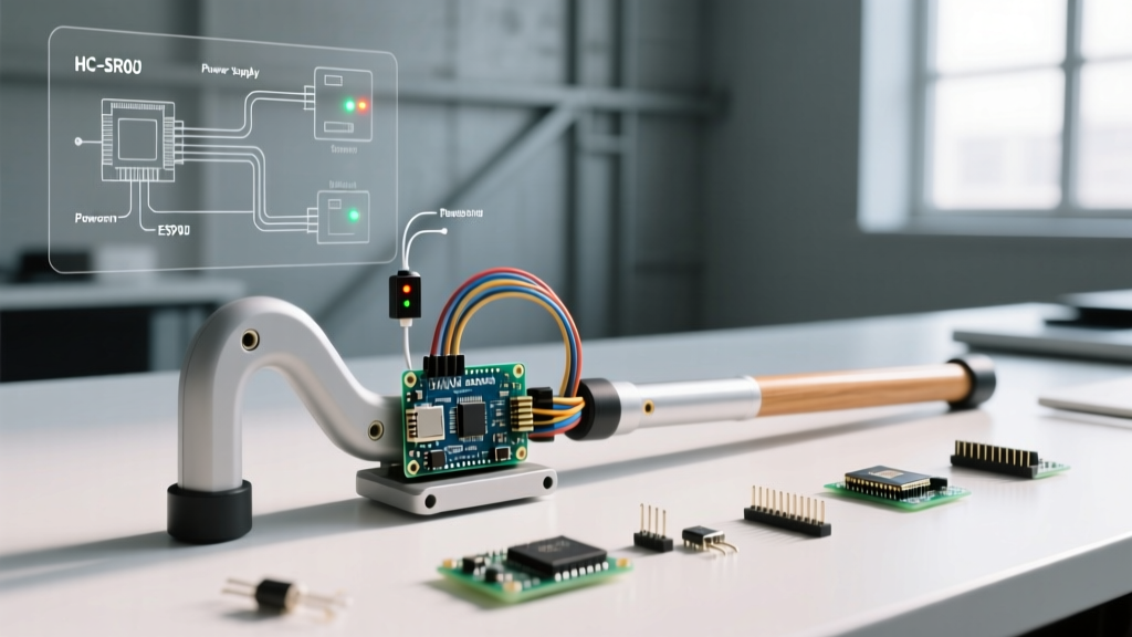

Project Overview: The Smart Assistive Cane
Building an arduino nano walking stick is one of the most rewarding first projects for embedded systems enthusiasts. It bridges the gap between abstract microcontroller programming and tangible, life-changing assistive technology. According to the World Health Organization, over 2.2 billion people globally have a near or distance vision impairment, making Electronic Travel Aids (ETAs) a critical area for DIY innovation.
In this setup and first project tutorial, we will construct a smart cane that uses ultrasonic proximity detection to translate physical obstacles into haptic feedback (vibration). Unlike generic LED-blinking tutorials, this guide addresses real-world engineering challenges: power management, GPIO current protection, and acoustic edge cases.
Bill of Materials (2026 Pricing & Sourcing)
To keep the walking stick lightweight and cost-effective, we are bypassing bulky 9V batteries and standard breadboards in favor of a permanent, compact soldered build.
| Component | Model / Specification | Est. Price (2026) | Engineering Notes |
|---|---|---|---|
| Microcontroller | Arduino Nano V3.0 (ATmega328P) | $6.50 (Clone) / $24.00 (Official) | Clone boards often use the CH340 USB driver; install drivers accordingly. |
| Proximity Sensor | HC-SR04 Ultrasonic (40kHz) | $1.80 | Effective range: 2cm to 400cm. Blind spot under 2cm. |
| Haptic Feedback | 3V-5V Coin Vibration Motor (10mm) | $1.20 | Requires a transistor driver. Do NOT connect directly to Nano GPIO. |
| Motor Driver | 2N2222 NPN Transistor + 1N4007 Diode | $0.30 | Flyback diode is mandatory to prevent back-EMF from frying the Nano. |
| Power Source | 18650 Li-Ion Cell (e.g., Molicel P28A) | $5.50 | Provides 3.7V nominal; high energy density for all-day use. |
| Power Regulation | MT3608 Boost Converter Module | $1.50 | Steps 3.7V up to a stable 5.2V for the Nano's 5V rail. |
| Chassis | 8mm Carbon Fiber Kite Tube (120cm) | $12.00 | Lightweight, rigid, and dampens vibration better than PVC. |
Why the Arduino Nano for Wearable Assistive Tech?
While the ESP32 offers Wi-Fi and Bluetooth, an ETA does not require cloud connectivity for basic obstacle avoidance. The Arduino Nano remains the optimal choice for this specific application due to three factors:
- Form Factor: At 18x48mm and roughly 7 grams, it disappears inside a cane handle.
- Power Efficiency: The ATmega328P can be put into deep sleep modes, drawing microamps between sensor pings, vastly extending the 18650 battery life compared to power-hungry Wi-Fi MCUs.
- 5V Logic: The HC-SR04 operates natively at 5V. Using a 3.3V board like the Raspberry Pi Pico or ESP32 requires logic level shifters, adding unnecessary weight and wiring complexity to a first project.
Wiring & Circuit Protection (The Transistor Rule)
Critical Warning: A common failure mode in beginner haptic projects is connecting a vibration motor directly to a digital PWM pin. Motors draw 100mA+ on startup; the Nano's GPIO pins are limited to 20mA (40mA absolute max). Direct connection will permanently destroy the ATmega328P's internal silicon traces.
We use a 2N2222 NPN transistor as a switch, controlled by the Nano's PWM Pin 3. The 1N4007 flyback diode is placed in reverse-bias across the motor terminals to safely route inductive voltage spikes back into the motor loop when the transistor switches off.
Pinout Configuration
- HC-SR04 VCC: Nano 5V
- HC-SR04 GND: Nano GND
- HC-SR04 Trig: Nano Pin 9
- HC-SR04 Echo: Nano Pin 10 (Use a 1k/2k voltage divider if using a 3.3V board, but not needed for Nano)
- Motor Positive: Nano 5V
- Motor Negative: 2N2222 Collector
- 2N2222 Base: Nano Pin 3 (via 220Ω resistor)
- 2N2222 Emitter: Nano GND
Step-by-Step Assembly Guide
Step 1: Mounting the Ultrasonic Sensor
The physical placement of the HC-SR04 dictates the success of the walking stick. If mounted too low and angled downward, the sensor will constantly detect the floor ('ground clutter'), causing the motor to vibrate continuously. Solution: Mount the sensor at waist height (approx. 90cm from the ground) and angle it 5 degrees upward. The 15-degree acoustic beam width will still catch knee-level obstacles like coffee tables and curbs without triggering on the pavement.
Step 2: Handle Integration & Haptics
3D print a custom handle using TPU (flexible filament) or PETG. Embed the vibration motor directly into the grip zone using hot glue. The Nano and MT3608 boost converter should be housed in a sealed compartment near the base of the handle to maintain a balanced center of gravity.
Step 3: Power Management Setup
Before connecting the battery, use a multimeter and a small flathead screwdriver to adjust the potentiometer on the MT3608 boost module. Set the output exactly to 5.1V. This accounts for minor voltage drops across the Nano's internal Schottky diode if you were to power it via the 5V pin directly.
The Code: Proximity Detection & Haptic Scaling
The firmware uses the pulseIn() function to measure the echo return time. We then map the distance (from 150cm down to 10cm) to a PWM duty cycle (0 to 255). As the user gets closer to an obstacle, the vibration intensity smoothly scales up.
const int trigPin = 9;
const int echoPin = 10;
const int motorPin = 3;

long duration;
int distance;

void setup() {
  pinMode(trigPin, OUTPUT);
  pinMode(echoPin, INPUT);
  pinMode(motorPin, OUTPUT);
  Serial.begin(9600);
}

void loop() {
  // Clear the trigger pin
  digitalWrite(trigPin, LOW);
  delayMicroseconds(2);

  // Trigger a 10us pulse
  digitalWrite(trigPin, HIGH);
  delayMicroseconds(10);
  digitalWrite(trigPin, LOW);

  // Read the echo pin
  duration = pulseIn(echoPin, HIGH, 30000); // 30ms timeout
  distance = duration * 0.034 / 2;

  // Map distance to PWM (closer = stronger vibration)
  if (distance > 150 || distance == 0) {
    analogWrite(motorPin, 0); // Safe zone or timeout
  } else {
    int pwmValue = map(distance, 10, 150, 255, 0);
    pwmValue = constrain(pwmValue, 0, 255);
    analogWrite(motorPin, pwmValue);
  }

  delay(50); // 20Hz polling rate is sufficient for walking speed
}
Calibration and Edge Case Troubleshooting
Real-world deployment of an arduino nano walking stick reveals physics limitations that breadboard testing hides. Here is how to handle the most common failure modes:
1. The 'Winter Coat' Problem (Acoustic Dampening)
Ultrasonic sensors at 40kHz struggle with soft, angled, or sound-absorbing materials. A heavy winter puffer jacket can reduce HC-SR04 return echoes by up to 60%, causing false negatives (failing to vibrate when approaching a person). Fix: In the code, increase the polling rate to 50Hz and implement a rolling average filter. For hardware redundancy, add a Sharp GP2Y0A21YK0F Infrared sensor, which relies on light reflection rather than sound, bypassing acoustic dampening entirely.
2. Battery Sag and Brownouts
Vibration motors draw high current spikes. If your 18650 cell is older or has high internal resistance, this spike can cause the voltage to sag below 4.5V, triggering the Nano's brownout detection (BOD) and causing random reboots. Fix: Solder a 470µF electrolytic capacitor across the 5V and GND rails near the motor to act as a local energy reservoir during current spikes.
3. Acoustic Shadows and Thin Objects
Thin objects like chair legs or poles may fall between the 15-degree acoustic lobes of the sensor. To mitigate this, mount two HC-SR04 sensors: one facing dead ahead, and one angled 20 degrees to the right (the side most likely to encounter doorframes and shelves). Interleave their trigger pulses in the code to prevent acoustic crosstalk.
Further Reading & References
- Arduino Official Nano Hardware Documentation - Detailed schematics and ATmega328P pin current limits.
- SparkFun Ultrasonic Sensor Guide - Deep dive into the physics of 40kHz acoustic wave propagation.
- WHO Visual Impairment Fact Sheet - Global statistics on mobility challenges and assistive tech needs.