
The 1 wire temperature sensor—most notably the Maxim Integrated (now Analog Devices) DS18B20—is a staple in DIY electronics, HVAC monitoring, and industrial automation. Its ability to communicate over a single data line makes it incredibly elegant, but that same simplicity masks complex underlying timing and electrical requirements. When a 1-wire bus fails, it rarely does so silently; instead, it spits out bizarre, hardcoded error values or drops devices entirely.
According to the Analog Devices DS18B20 Datasheet, the sensor operates with a strict timing protocol. A microsecond-level miscalculation in your microcontroller's code, or a slight capacitive load on your wiring, can corrupt the entire ROM read sequence.
This guide bypasses basic tutorials and dives straight into the electrical and programmatic failure modes of 1-wire networks. Whether you are wiring a single sensor to an Arduino or deploying a 50-meter bus with multiple nodes on a Raspberry Pi, understanding the physical layer is the key to stable readings.
Diagnostic Matrix: Decoding Sensor Error Codes
Unlike analog thermistors that drift gradually, a digital 1 wire temperature sensor will output specific, hardcoded values when it encounters a fault. Recognizing these values is the first step in isolating whether your issue is physical, electrical, or programmatic.
| Observed Reading | Hardware / Software Fault | Corrective Action |
|---|---|---|
| 85°C (185°F) | Power-On Reset (POR) default value. The sensor received power, but the ADC conversion command was never issued, timed out, or failed due to voltage sag. | Verify requestTemperatures() is called. Check for parasitic power voltage sag during conversion. |
| -127°C | Open circuit on the data line, missing pull-up resistor, or broken ground connection. The microcontroller reads the line as permanently HIGH. | Verify 4.7kΩ pull-up resistor. Check continuity from GND pin to microcontroller ground. |
| -196°C or NaN | Data line shorted to ground, or severe EMI corruption causing the internal CRC check to fail and the library to return an error. | Inspect for solder bridges. Add a 100nF decoupling capacitor across VDD and GND. |
| Wild Fluctuations | High cable capacitance degrading the signal rise time, or ground loops introducing noise into the analog-to-digital conversion stage. | Use Cat5e twisted pair, reduce cable length, or implement an active MOSFET pull-up. |
The Physical Layer: Pull-Up Resistors and Signal Integrity
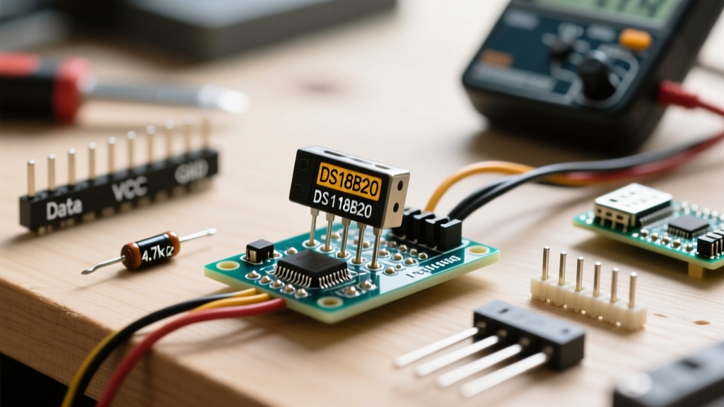
The 1-wire protocol utilizes an open-drain architecture. This means the sensor can only pull the data line LOW (to ground); it cannot drive it HIGH. To return the line to a HIGH state (logic 1), an external pull-up resistor connected to the supply voltage (VCC) is mandatory.
The 4.7kΩ Rule and Capacitive Loading
The standard schematic calls for a 4.7kΩ resistor. However, this value is only optimal for short runs (under 5 meters) with one or two sensors. Every meter of cable adds parasitic capacitance to the data line. When the microcontroller releases the line (allowing it to float HIGH), the 4.7kΩ resistor must charge this capacitance. If the cable is too long, the RC time constant increases, and the voltage rises too slowly. The microcontroller samples the line before it crosses the logic HIGH threshold, resulting in bit errors and CRC failures.
Pro-Tip for Long Runs: If you are running cables beyond 10 meters, drop the pull-up resistor to 2.2kΩ or even 1kΩ to provide more current and charge the line capacitance faster. For runs exceeding 30 meters, abandon passive resistors entirely and use an active pull-up circuit driven by a MOSFET, or a dedicated 1-Wire master IC like the DS2482.
Decoupling Capacitors: The Unsung Heroes
A frequent mistake in DIY 1 wire temperature sensor builds is omitting local decoupling. During the temperature conversion phase, the internal ADC draws a sudden spike of current (up to 1.5mA). If the power supply traces have high impedance, this current draw causes a localized voltage drop, resetting the sensor's digital logic mid-conversion. Always solder a 100nF (0.1µF) ceramic capacitor directly across the VDD and GND pins of the sensor, as close to the TO-92 package as physically possible.
Parasitic Power Mode: Wiring and Pitfalls
The DS18B20 can operate in 'parasitic power' mode, drawing its operating current directly from the data line, eliminating the need for a dedicated VCC wire. To use this mode, you tie the VDD pin (Pin 3) directly to GND (Pin 1).
While this saves copper, it introduces severe electrical challenges. When the microcontroller issues the 'Convert T' command, the sensor requires a steady 1.5mA for up to 750ms (at 12-bit resolution). A standard 4.7kΩ pull-up resistor connected to 5V can only supply roughly 1mA. This is insufficient, causing the sensor's internal storage capacitor to drain, leading to the dreaded 85°C POR error.
The Strong Pull-Up Requirement: To make parasitic mode work reliably, the microcontroller must activate a 'strong pull-up' immediately after sending the conversion command. This is typically achieved using a P-channel MOSFET that directly connects the data line to VCC, bypassing the 4.7kΩ resistor and delivering the necessary current. As noted in the PJRC OneWire Library documentation, failing to implement a strong pull-up in parasitic mode is the number one cause of intermittent bus failures.
Software Timing and the Infamous 85°C Bug
If your hardware is sound but you are consistently reading 85°C on startup, you are witnessing the Power-On Reset (POR) value. The sensor's scratchpad registers default to 85°C when powered up. If your code reads the scratchpad before the ADC conversion is complete, you will read this default value.
Blocking vs. Non-Blocking Code
When using the popular DallasTemperature library on Arduino, the requestTemperatures() function is blocking by default. It sends the conversion command and then halts the microcontroller for 750ms. While this guarantees the conversion is finished, it freezes your entire system.
Many developers switch to asynchronous (non-blocking) mode using setWaitForConversion(false). If you do this, you must manually track the elapsed time using millis() before calling getTempCByIndex(). If your loop executes too quickly and polls the sensor before the 750ms window closes, you will read the 85°C default. Always implement a state machine or a strict timing delay when using asynchronous conversions.
CRC Validation
Electrical noise can flip bits during the 64-bit ROM read or the 9-byte scratchpad read. The 1-wire protocol includes a Cyclic Redundancy Check (CRC) byte to verify data integrity. Many basic tutorials ignore the CRC. In electrically noisy environments (like near HVAC contactors or VFD motors), you must enable CRC checking in your library. If the CRC fails, discard the reading and poll again rather than logging a false temperature spike.
Advanced Field Fixes for Industrial & Outdoor Setups
When deploying a 1 wire temperature sensor network outdoors or in industrial panels, environmental factors compound electrical flaws.
- Twisted Pair is Mandatory: Never use flat ribbon cables or untethered stranded wire for long runs. Use Cat5e or Cat6 Ethernet cable. Dedicate one twisted pair exclusively to the Data line and Ground, and use the remaining pairs for VCC and Ground. The twisting cancels out common-mode electromagnetic interference.
- Galvanic Isolation: If your sensors are submerged in conductive liquids (like saltwater pools or hydroponic reservoirs) and connected to a mains-powered PC, ground loops can destroy the microcontroller. Use a digital isolator IC (like the ISO7721) between the microcontroller and the 1-wire bus to break the electrical continuity while preserving the data signal.
- Topologies Matter: The 1-wire bus is highly sensitive to stubs. Avoid 'star' topologies where multiple cables branch out from a central point. Reflections from the unterminated stubs will corrupt the data edges. Always wire your sensors in a linear 'daisy-chain' topology, keeping the distance from the main trunk to each sensor (the stub length) under 3 meters.
Mastering the 1 wire temperature sensor requires looking past the simplicity of the three-pin interface. By respecting the RC time constants of your cabling, providing adequate decoupling, and handling asynchronous timing correctly in your firmware, you can build a thermal monitoring network that is as robust as any industrial 4-20mA system.
For further reading on bus topologies and signal integrity, refer to the Adafruit DS18B20 Temperature Sensing Guide and the official Analog Devices application notes on 1-Wire networking.