
The Direct Answer: Testing and Selecting Variable Resistors
To test a rheostat or potentiometer, set your digital multimeter (DMM) to the Ohms (Ω) function, measure the two fixed endpoints to verify total resistance, and then sweep the wiper terminal to confirm smooth, linear tracking without dead spots. A good reading matches the component’s nameplate value (±10% to ±20% tolerance) and transitions smoothly from near 0Ω to the total resistance as you rotate the shaft. If you are replacing a failed component, the decision is straightforward: use a 3-terminal potentiometer (like the Bourns 3590P-1-103L) for low-power voltage division and signal trimming, and use a 2-terminal wirewound rheostat (like the Ohmite RJS 50E) for high-current load control and motor speed regulation.
Multimeter Setup and Safety Categories for Variable Resistors
Before touching any probes to the component, you must configure your meter correctly and assess the safety environment. Variable resistors are often found in mains-adjacent equipment, such as ceiling fan speed controllers, HVAC control boards, and tube amplifier bias circuits.
Never measure resistance on a live circuit. If the rheostat or potentiometer is connected to mains voltage, turn off the breaker, apply lockout/tagout, and verify the circuit is dead with a non-contact voltage tester. Furthermore, tube amplifiers and motor controllers contain high-voltage capacitors that can hold a lethal charge long after power is removed. Discharge all capacitors through a proper bleeder resistor before probing.
Meter Configuration Block
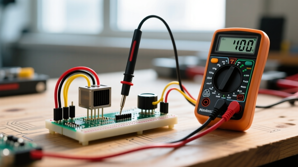
- Dial Position: Set to Resistance (Ω). If your meter is manual-ranging, start at the 20kΩ or 200kΩ range to capture standard 10kΩ or 100kΩ audio pots without over-ranging.
- Lead Jacks: Black lead in COM, Red lead in VΩ (or Ω). Do not use the current (A/mA) jacks, as this will create a dead short across the wiper.
- Secondary Mode: Enable the continuity beeper (diode symbol with sound waves) for a quick wiper-to-end-terminal short check at the absolute minimum rotation.
Understanding CAT Ratings for In-Circuit Checks
If you are performing a continuity check without fully removing the component from a mains-powered appliance, your meter must be rated for the environment. According to Fluke’s measurement category guidelines, testing a ceiling fan speed controller or a hardwired HVAC thermostat requires a minimum CAT II rated meter and probes. If you are testing a heavy-duty industrial motor rheostat at the main disconnect panel, you must use CAT III or CAT IV rated test leads with the proper exposed tip length (usually 4mm or less) to prevent arc flash incidents. For bench testing a desoldered component, CAT ratings are irrelevant, but standard probe integrity still matters.
Step-by-Step Probe Placement and Expected Readings
A standard potentiometer has three terminals: Pin 1 (Counter-Clockwise end), Pin 2 (Wiper), and Pin 3 (Clockwise end). A rheostat is typically just a two-terminal device utilizing the wiper and one end terminal, though it may be wired from a 3-terminal pot. Follow these numbered steps for a definitive diagnosis.
- Total Resistance Check (Pin 1 to Pin 3): Place probes on the two outer terminals. Rotate the shaft; the reading should remain completely static. This confirms the resistive track is intact.
- Wiper Sweep Check A (Pin 1 to Pin 2): Place one probe on Pin 1 and the other on the center Wiper (Pin 2). Rotate the shaft slowly from fully CCW to fully CW. The resistance should climb smoothly from near 0Ω up to the total resistance value.
- Wiper Sweep Check B (Pin 3 to Pin 2): Move the probe from Pin 1 to Pin 3. Rotate the shaft in the same direction. The resistance should now drop smoothly from the total resistance down to near 0Ω.
- Wiper Contact Verification: Wiggle the shaft gently side-to-side without rotating it. The resistance reading should not jump or flutter.
Expected Reading Table: Good vs. Bad Values
Assuming a nominal 10,000Ω (10kΩ) linear (B-taper) potentiometer with a ±10% tolerance:
| Test Point | Shaft Position | Expected (Good) Reading | Bad Reading (Fault Indication) |
|---|---|---|---|
| Pin 1 to Pin 3 | Any position | 9.0kΩ to 11.0kΩ (Static) | OL / Infinite (Open track) or <1kΩ (Shorted track) |
| Pin 1 to Pin 2 | Fully CCW | 0Ω to 50Ω | >500Ω (Wiper contact failure / dirty track) |
| Pin 1 to Pin 2 | 50% Rotation | 4.5kΩ to 5.5kΩ | Erratic jumping, sudden spikes to OL (Dead spot) |
| Pin 1 to Pin 2 | Fully CW | 9.0kΩ to 11.0kΩ | Significantly lower than Pin 1-3 total (Internal short) |
Common Measurement Mistakes That Skew Results
When troubleshooting variable resistors, the component is often blamed for circuit failures when the actual error lies in the measurement technique. Avoid these three common pitfalls that yield misleading data.
1. Measuring In-Circuit (The Parallel Path Error)
If you measure a potentiometer while it is still soldered to a PCB, the multimeter injects a small test current that flows through all parallel paths on the board. If your 10kΩ pot is in parallel with a 5kΩ fixed resistor, your meter will read approximately 3.33kΩ, leading you to falsely conclude the pot is shorted or out of spec. Fix: Always desolder at least two of the three legs (or lift the component entirely) before measuring total resistance. For quick in-circuit checks, use the diode-test mode to check for semiconductor junctions, but rely on desoldered Ohms measurements for track verification.
2. Finger Resistance on High-Value Pots
When testing 1MΩ or 2.5MΩ audio taper potentiometers, the natural resistance of human skin (typically 50kΩ to 500kΩ depending on moisture) will parallel the component if your fingers touch both the probe tips and the metal shaft. This artificially drags the reading down. Fix: Use alligator clip test leads or hold the insulated probe shafts firmly without touching the metal tips or the component body.
3. Missing Wiper Noise (The DMM Averaging Trap)
Digital multimeters sample at a rate of 2 to 5 Hz. If a carbon track has a micro-second open circuit (a "dead spot") as the wiper passes over a physical scratch, the DMM’s averaging algorithm might completely miss the spike, showing a smooth transition. This causes severe audio "scratchiness" or motor stuttering in practice. Fix: For critical audio or precision servo applications, monitor the wiper with an oscilloscope while sweeping the shaft. If you only have a DMM, use the Min/Max capture mode while sweeping slowly to catch transient open-circuit spikes.
If a carbon-film potentiometer shows dead spots but the total end-to-end resistance is correct, the track is physically worn or oxidized. Spraying DeoxIT D5** (Hosa D5S-6)** contact cleaner into the wiper slot and rotating the shaft 50 times can restore contact. Do not use standard WD-40, which leaves a dielectric residue that will permanently ruin the track.
Diagnostic Decision Tree: Fault Finding and Component Selection
When a variable resistor fails, you must decide whether to clean it, replace it with an identical part, or substitute a different topology. Furthermore, hobbyists frequently confuse the application of rheostats and potentiometers. As detailed in All About Circuits’ guide to variable resistors, the physical construction dictates the application: pots are for voltage division, rheostats are for current limiting.
Use the following decision matrix to terminate your troubleshooting and select the exact replacement part.
| Symptom / Application Need | Diagnostic Condition | Action & Concrete Part Recommendation |
|---|---|---|
| Audio scratchiness / erratic sensor voltage | Total R is good, but wiper sweep shows micro-spikes on Min/Max DMM mode. | Clean or Replace Pot. Buy Bourns 3386P-1-103LF (10kΩ Cermet Trimpot) for PCB sensor trimming, or Alps RK09K series for audio panels. |
| Precision calibration drift (lab equipment) | Single-turn pot lacks resolution; 1-degree rotation changes voltage by 50mV. | Upgrade to Multi-Turn. Buy Bourns 3590P-1-103L (10kΩ, 10-turn wirewound). Provides 10x resolution for precise voltage division. |
| DC Motor speed control (12V-48V, >2A) | Standard 1/2W carbon pot melted or shaft seized due to high current. | Switch to Rheostat. Buy Ohmite RJS 50E (50Ω, 25W Wirewound Rheostat). Wire using only the wiper and one end terminal to handle high amperage. |
| Tube Amplifier Bias Adjustment | High voltage present; standard pot tracking is too coarse for safe bias setting. | Use High-Voltage Trimpot. Buy Bourns 3296W-1-102LF (1kΩ, 25-turn, 500V rating). Ensures safe, micro-adjustments without arcing. |
By matching the failure mode to the correct physical topology, you eliminate repeat failures. Remember that a potentiometer wired as a rheostat (by tying the wiper to the unused end terminal) can safely handle low-current variable resistance tasks, but a dedicated wirewound rheostat is strictly required when dissipating more than 1 or 2 watts of heat. Always verify the power rating (Watts) of your replacement using the formula P = I²R before soldering it into the circuit.