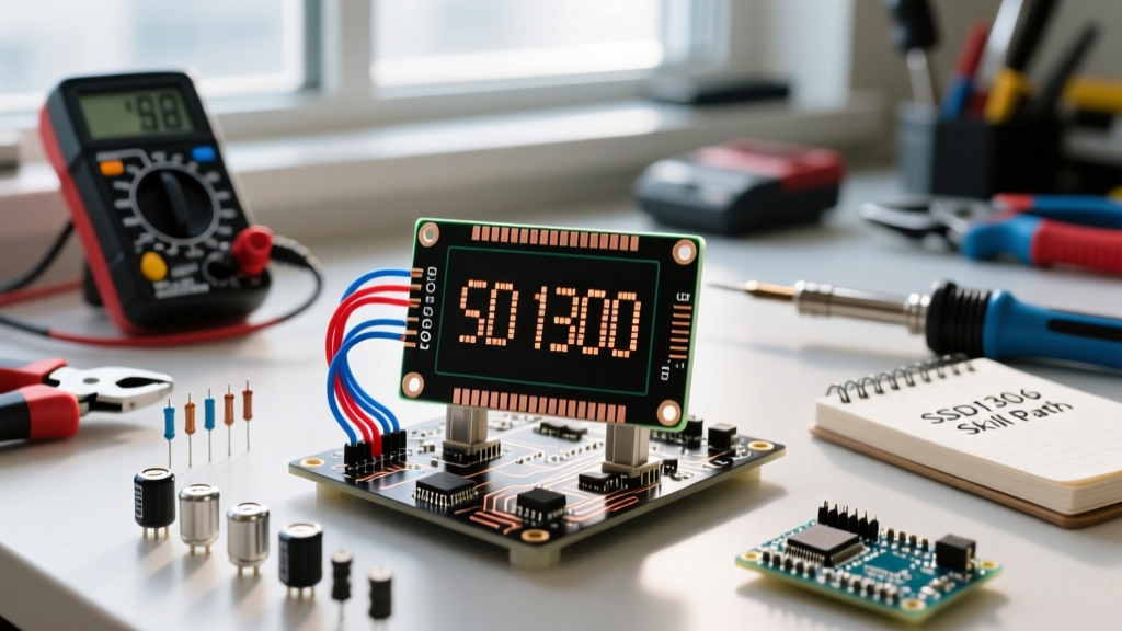

The SSD1306 OLED display is widely considered a rite of passage for electronics hobbyists, embedded engineers, and DIYers. Whether you are building a custom macro keypad, a smart home environmental dashboard, or a portable diagnostic tool, this monochrome marvel offers exceptional contrast, wide viewing angles, and low power consumption. However, moving from simply copying a basic wiring diagram to truly mastering the SSD1306 requires a structured, methodical approach. In this skill-building path, we will progress from physical hardware nuances to advanced memory-constrained rendering techniques, ensuring your displays are robust, fast, and reliable for any application.
Level 1: The Physical Layer - Hardware Realities
Before writing a single line of code, an embedded engineer must understand the physical constraints of the hardware. The most common SSD1306 modules found on the market are the 0.96-inch 128x64 and 128x32 variants, typically communicating via I2C or SPI. While the 4-pin I2C version is the most popular for its minimal wiring footprint, it introduces specific electrical challenges that beginners often overlook.
The 5V Logic Myth and Level Shifting
A pervasive myth in the maker community is that cheap SSD1306 breakout boards are "5V compatible." While it is true that many boards include an AMS1117-3.3 LDO voltage regulator to handle a 5V power input, this regulator only protects the power rail. The I2C data lines (SDA and SCL) are often routed directly to the SSD1306 controller pins, which are strictly 3.3V logic devices according to the Solomon Systech official datasheet. Feeding 5V logic from an Arduino Uno or Mega into these pins forces current through the chip's internal ESD protection diodes. Over time, this degrades the silicon, leading to flickering, dead pixels, or total controller failure. To build robust systems, always use a bidirectional logic level shifter (like the BSS138 MOSFET-based shifters) or power your microcontroller at 3.3V using an ESP32 or a 3.3V Arduino Pro Mini.
I2C Addresses, Pull-Ups, and Bus Capacitance
The standard I2C address for the SSD1306 is 0x3C, though some manufacturers use 0x3D. If you are running multiple displays on a single bus, you will need to modify the hardware address by moving a tiny 0-ohm surface-mount resistor on the back of the PCB. Furthermore, I2C is an open-drain protocol that requires pull-up resistors. While many microcontrollers have internal pull-ups (often 20kΩ to 50kΩ), these are too weak for reliable high-speed communication. For a standard 400kHz I2C bus, you should install external 2.4kΩ or 4.7kΩ pull-up resistors on both SDA and SCL lines to combat bus capacitance and ensure sharp signal edges.
Level 2: The Logic Layer - Software and Memory Constraints
Once the hardware is correctly wired, the next hurdle is software architecture. Driving a 128x64 monochrome display requires a framebuffer—a contiguous block of memory where each bit represents a single pixel. For a 128x64 display, this requires exactly 1,024 bytes (128 * 64 / 8) of SRAM. If you are using an ATmega328P-based board (like the Arduino Uno), you only have 2,048 bytes of total SRAM. Allocating half of your available memory just to the display leaves very little room for sensor buffers, network stacks, or complex logic.
Library Selection: Adafruit vs. U8g2
Choosing the right library is critical for managing these memory constraints. Below is a comparison of the two industry-standard libraries for the SSD1306.
| Feature | Adafruit_SSD1306 | U8g2 (by olikraus) |
|---|---|---|
| SRAM Footprint | High (Full 1024-byte buffer required) | Flexible (Full, Page, or Terminal modes) |
| Font Flexibility | Limited (Relies on Adafruit GFX fonts) | Massive (Hundreds of built-in international fonts) |
| Rendering Engine | Simple immediate-mode drawing | Advanced retained-mode with hardware SPI support |
| Learning Curve | Very Low (Beginner friendly) | Moderate to High (Requires understanding of memory modes) |
For beginners and rapid prototyping, the Adafruit OLED Breakouts guide and their associated library provide an excellent starting point. However, as your project grows in complexity, migrating to U8g2 is highly recommended. The U8g2 Wiki details how to use the "Page Buffer" mode (e.g., U8G2_SSD1306_128X64_NONAME_1_HW_I2C), which reduces the SRAM requirement from 1,024 bytes down to just 128 bytes by rendering the screen in horizontal strips. This is a game-changer for memory-starved microcontrollers.
Level 3: The Mastery Layer - Optimization and Longevity
True mastery of the SSD1306 involves looking beyond basic drawing commands and focusing on display longevity, bare-metal optimization, and visual polish.
The Charge Pump Initialization Sequence
If you ever decide to write your own bare-metal I2C driver without relying on heavy libraries, you must understand the SSD1306's internal charge pump. The OLED pixels require a higher voltage (around 7V to 9V) to illuminate, which the chip generates internally from the 3.3V logic rail using a DC-DC converter. During initialization, you must send the specific command sequence 0x8D followed by 0x14 to enable this charge pump. If you omit this step, the I2C communication will succeed, but the screen will remain completely black. Many developers waste hours debugging their I2C wiring when the issue is simply a missing charge pump command in their initialization array.
Preventing Burn-In with Pixel Shifting
OLED displays are susceptible to burn-in, where static elements (like battery icons or Wi-Fi status bars) permanently degrade the organic compounds in specific pixels, leaving a ghost image. To combat this in a production environment, implement a software-based pixel-shifting algorithm. By shifting the entire framebuffer origin by 1 or 2 pixels in a circular pattern every 60 seconds, you distribute the wear evenly across the panel. Additionally, utilize the SSD1306's hardware sleep command (0xAE) to turn off the display panel entirely when the device is idle, rather than just drawing a black screen (which still powers the organic diodes).
Beware the SH1106 Imposter
When sourcing displays from online marketplaces, you may encounter modules labeled as SSD1306 that actually contain the SH1106 driver chip. While largely compatible, the SH1106 features a slightly larger internal RAM of 132x64. This results in a 2-pixel horizontal offset when using standard SSD1306 libraries, causing the left edge of your graphics to be clipped or wrapped. Always run an I2C ID check or use a library that includes a specific SH1106 fallback routine if your final image appears misaligned.
Troubleshooting Matrix: Real-World Failure Modes
Even experienced engineers encounter issues when integrating the SSD1306. Use this diagnostic matrix to quickly resolve common roadblocks:
- Symptom: Display is completely blank, but I2C Scanner finds the device at 0x3C.
Root Cause: Charge pump not enabled, or the OLED panel is physically disconnected from the ribbon cable (common on cheap clones).
Solution: Verify the 0x8D/0x14 initialization commands. Inspect the yellow ribbon cable for micro-tears. - Symptom: I2C Scanner returns no devices, or returns random fluctuating addresses.
Root Cause: Missing pull-up resistors, excessive bus capacitance, or a blown 3.3V LDO on the breakout board.
Solution: Add 4.7kΩ external pull-ups. Measure the VCC pin with a multimeter to ensure it reads exactly 3.3V. - Symptom: Screen updates are incredibly slow and visibly tear or scroll.
Root Cause: Using software I2C instead of hardware I2C, or redrawing the entire screen for minor text updates.
Solution: Switch to hardware I2C pins (A4/A5 on Uno). Use partial update functions or bounding-box redraws instead of callingdisplay.clearDisplay()every loop iteration. - Symptom: Random white noise or static fills the bottom half of the screen.
Root Cause: SPI/I2C clock speed exceeds the physical trace limits of the breadboard, causing bit-flipping in the controller RAM.
Solution: Lower the I2C clock speed from 400kHz to 100kHz in your microcontroller's Wire library settings.
Conclusion
Mastering the SSD1306 OLED display is about more than just getting pixels to light up; it is about understanding the intersection of hardware limitations, memory management, and long-term reliability. By respecting the 3.3V logic thresholds, choosing the right memory-optimized library, and implementing protective software routines like pixel-shifting, you elevate your project from a fragile prototype to a professional-grade embedded system. Keep this skill-building path in mind as you design your next user interface, and your displays will remain crisp, responsive, and reliable for years to come.