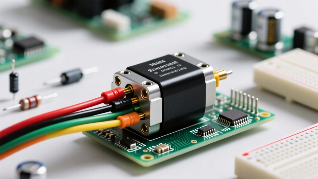

The Anatomy of a Standard Servo Pinout
Understanding the standard servo pinout is a fundamental rite of passage for robotics hobbyists, RC enthusiasts, and automation engineers. At its core, a standard hobby servo relies on a simple three-wire interface to receive power and positional commands. However, assuming that all three-pin connectors are universally standardized is one of the most common and costly mistakes in electronics prototyping. Misinterpreting the servo pinout can instantly destroy your microcontroller, melt your wiring harness, or permanently brick the internal H-bridge motor driver inside the servo casing.
A standard hobby servo connector (often referred to as a JR-style connector) features three pins spaced at a standard 2.54mm (0.1-inch) pitch. These pins serve distinct, non-interchangeable functions:
- Ground (GND): The common reference point for both the power circuit and the PWM signal.
- Power (VCC): The positive voltage rail, typically expecting 4.8V to 6.0V for standard servos, or up to 8.4V for High-Voltage (HV) models.
- Signal (PWM): The control wire that receives a pulse-width modulated square wave (usually 50Hz) to dictate the angular position of the output shaft.
While the physical layout of the JR connector is uniform, the lack of a built-in polarizing key means the connector can easily be plugged in backward or upside down. This is where a deep understanding of the servo pinout transitions from a theoretical concept to a critical safety requirement.
Brand-Specific Color Codes: A Hazard Map
The most dangerous aspect of the servo pinout is the lack of a universal color code standard. While the physical pin order on a JR connector is almost always Signal-VCC-GND (or GND-VCC-Signal depending on the male/female perspective), the wire insulation colors vary wildly between manufacturers. Plugging a Futaba servo into a harness wired for Hitec servos without verifying the pinout will reverse the polarity, sending positive voltage directly into the microcontroller's ground plane.
Below is a comparison chart of the most common servo wiring color codes encountered in the field:
| Manufacturer | Signal Wire | VCC (Positive) | GND (Negative) | Connector Type Notes |
|---|---|---|---|---|
| Hitec / JR / Spektrum | White or Yellow | Red | Black | Standard JR 3-pin, no lock |
| Futaba | White | Red | Black | J-Type with polarizing tab |
| Savox | Yellow | Red | Brown or Black | Standard JR 3-pin |
| Tower Pro (SG90/MG996R) | Yellow / Orange | Red | Brown / Dark Grey | Standard JR 3-pin |
As noted in the Pololu Servo Guide, Futaba connectors feature a small plastic tab (the J-type connector) designed to prevent reverse insertion. However, many aftermarket adapters and custom PCBs strip this safety feature away to maintain compatibility with JR-style plugs, placing the burden of safety entirely on the builder's knowledge of the wire colors.
Critical Failure Modes: How Incorrect Pinouts Destroy Hardware
When the servo pinout is misinterpreted, the resulting electrical faults are usually catastrophic. Here are the specific failure modes you must design your circuits to prevent:
1. Reverse Polarity on the Servo
If VCC and GND are swapped at the servo end, the internal electronics are subjected to negative voltage. While some premium digital servos include a reverse-polarity protection diode, standard analog servos (like the ubiquitous SG90) do not. The internal motor driver IC (often a BA668 or similar dual H-bridge) will instantly short out, and the carbon track potentiometer used for positional feedback may overheat and melt, permanently jamming the servo.
2. Backfeeding the Microcontroller
If the servo pinout is reversed at the microcontroller header (e.g., plugging the servo's VCC into the Arduino's GND pin, and the servo's GND into the 5V pin), the servo's internal circuitry will attempt to pull current backward through the microcontroller's voltage regulator. This bypasses the regulator's protection diodes, often resulting in the thermal shutdown or physical cracking of the onboard linear regulator (such as the NCP1117).
3. Signal Pin Overvoltage
The PWM signal pin on a servo is routed directly to the input of an internal microcontroller or timing IC. If a wiring fault accidentally bridges the VCC rail (6.0V) to the Signal pin, it will exceed the maximum GPIO tolerance of the internal IC, frying the servo's logic board while leaving the motor driver intact—a particularly frustrating failure mode to diagnose.
Current Draw and BEC Safety: The Hidden Pinout Trap
A common misconception among beginners is that the VCC pin on a servo is merely a voltage reference. In reality, the VCC pin is a high-current power delivery rail. The SparkFun Servo Hookup Guide emphasizes that servos draw massive amounts of current, particularly when stalling or starting under load.
Consider the current requirements of popular servo models:
- Micro Servo (SG90): ~10mA at rest, but up to 700mA during a stall condition.
- Standard Metal Gear (MG996R): ~10mA at rest, but up to 2.5A during a stall condition.
- High-Torque Digital (Savox SC-1258MG): Can spike past 4.5A瞬间 during rapid directional changes.
Safety Warning: Never power a standard or high-torque servo directly from the 5V pin of an Arduino, ESP32, or Raspberry Pi. The onboard USB polyfuse or linear regulator will overheat, drop voltage, and cause the microcontroller to brownout and reset continuously.
The Best Practice Solution: Use an external BEC (Battery Eliminator Circuit) or a dedicated DC-DC buck converter rated for at least 5A continuous current. Wire the BEC's VCC and GND directly to the servo's power rails, and ensure that the BEC's GND is tied directly to the microcontroller's GND. This shared ground is mandatory; without it, the PWM signal lacks a common reference point, leading to signal jitter and unpredictable servo movement.
Signal Isolation and Logic Level Best Practices
The third pin in the servo pinout—the Signal wire—requires careful attention to logic levels. Most modern digital servos are highly tolerant and will reliably trigger on a 3.3V PWM signal from an ESP32 or Raspberry Pi. However, older analog servos and certain industrial-grade high-voltage servos strictly require a 5V logic threshold to register the pulse.
If you are designing a permanent installation or an industrial prototype, follow these safety and reliability best practices for the signal pin:
- Use Optoisolators for High-Voltage Setups: If you are driving 7.4V or 12V industrial servos, use an optoisolator (like the 6N137) or a logic-level MOSFET to isolate the microcontroller's 3.3V GPIO from the servo's signal pin. This prevents high-voltage transients generated by the servo's motor from traveling back up the signal wire and destroying your host controller.
- Implement Pull-Down Resistors: Microcontroller GPIO pins often float during the boot sequence before the firmware initializes the PWM peripheral. This floating state can cause the servo to twitch violently, potentially damaging the mechanical gears or the attached payload. Adding a 10kΩ pull-down resistor between the Signal pin and GND ensures the servo remains limp and safe during system boot.
- Twisted Pair Routing: In environments with high electromagnetic interference (EMI), such as near large brushless motors or RF transmitters, route the Signal and GND wires as a twisted pair. This minimizes the loop area and prevents EMI from inducing false PWM pulses, which could cause the servo to snap to an unintended position.
Mastering the servo pinout goes far beyond memorizing wire colors. By respecting the current demands of the VCC rail, ensuring common grounds, and protecting the delicate signal pin from transients, you transition from simply making motors spin to engineering robust, fail-safe electromechanical systems.


