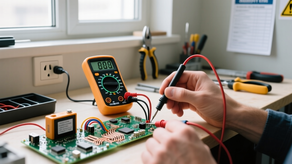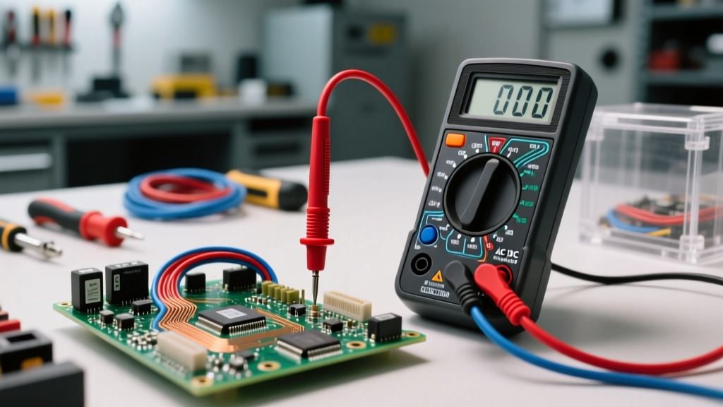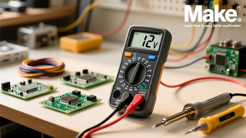

When you first unbox a digital multimeter (DMM), the array of cryptic symbols, dial settings, and probe ports can be deeply intimidating. However, learning how to use a tester multimeter is the single most important foundational skill for any DIY electronics enthusiast, maker, or apprentice electrician. Whether you are debugging an Arduino circuit, checking a blown automotive fuse, or verifying a wall outlet, this tool is your primary window into the invisible world of electricity.
In this comprehensive beginner tutorial, we will bypass the confusing jargon and focus on practical, real-world applications. We will cover exact dial settings, probe placements, and the critical safety protocols required to keep both you and your equipment safe from catastrophic failure.
The Anatomy of a Digital Multimeter: Ports and Probes
Before turning the dial, you must understand where to plug in your test leads. A standard manual-ranging multimeter (like the highly popular beginner-friendly AstroAI DM6000AR) typically features three or four input jacks at the bottom:
- COM (Common): This is the ground or reference point. Your black probe always goes here, regardless of what you are measuring.
- VΩmA (Voltage, Resistance, Milliamps): Your red probe plugs into this port when measuring voltage (AC or DC), resistance (Ohms), continuity, and small currents (usually under 200mA).
- 10A (10 Amps): The red probe moves to this dedicated port only when you need to measure high current (above 200mA up to 10 Amps). This port bypasses the internal delicate shunt resistor to prevent the meter from catching fire.
Pro-Tip on Probe Maintenance: Over time, probe tips oxidize and accumulate flux residue, leading to erratic resistance readings. Clean your probe tips regularly with isopropyl alcohol and a Scotch-Brite pad to ensure a solid electrical connection.
Safety First: Demystifying CAT Ratings
Many beginners buy cheap, unbranded multimeters from online marketplaces without realizing the severe safety risks. Multimeters are categorized by Measurement Categories (CAT ratings), which define their ability to withstand transient voltage spikes (like inductive kickbacks or nearby lightning strikes).
- CAT II: Safe for single-phase receptacle plug-in loads (e.g., testing a toaster or a desktop PC power supply).
- CAT III: Safe for three-phase distribution, including single-phase commercial lighting and hardwired appliances. If you plan to test residential wall outlets or breaker panels, a CAT III 600V rated meter (like the Fluke 115) is the absolute minimum safety standard.
- CAT IV: Used for three-phase utility connections and outdoor service entrances.
For a deep dive into electrical safety standards, refer to the multimeter basics guide by Fluke, which outlines why internal arc-blast containment is just as important as the voltage rating itself.
Step-by-Step: Measuring Voltage (The Most Common Task)
Voltage is the electrical 'pressure' pushing electrons through a circuit. It is measured in parallel, meaning you simply touch the probes across two points without breaking the circuit.
1. Measuring DC Voltage (Batteries and Logic Boards)
Direct Current (DC) flows in one direction. You will use this setting for batteries, solar panels, and microcontrollers like the Raspberry Pi or Arduino.
- Plug the black probe into COM and the red probe into VΩmA.
- Turn the dial to the DC Voltage setting (denoted by a V with a solid and dashed line above it, or simply V⎓).
- If using a manual-ranging meter, select a range higher than your expected voltage. For a standard 9V battery, choose the 20V setting.
- Touch the red probe to the positive (+) terminal and the black probe to the negative (-) terminal.
- Note: If you reverse the probes on a DC circuit, a digital multimeter will simply display a negative number (e.g., -9.0V). It will not damage the meter.
2. Measuring AC Voltage (Wall Outlets and Mains)
Alternating Current (AC) changes direction periodically. This is what comes out of your wall outlets.
- Keep probes in the same ports (COM and VΩmA).
- Turn the dial to AC Voltage (V~ or VAC). Select the 600V range on a manual meter to safely accommodate 120V (US) or 230V (EU) mains.
- Insert the probes into the hot and neutral slots of the outlet. Because AC alternates, polarity does not matter; the reading will be positive regardless of probe orientation.
The Continuity Test: Your Best Friend for Troubleshooting
If you only learn one function on your DMM, make it continuity. Continuity tests whether a complete, unbroken path exists for electricity to flow. It is the fastest way to check blown fuses, broken internal wires, and cold solder joints.
Set your dial to the continuity symbol, which looks like a series of sound waves or a Wi-Fi icon. When you touch the two probe tips together, the multimeter should emit a loud beep and display a number very close to 0.00 (indicating near-zero resistance).
Practical Application - Testing a Glass Fuse:
Place one probe on each metal cap of the fuse. If the meter beeps, the fuse is intact. If the meter displays OL (Over Limit) and remains silent, the internal filament is broken, and the fuse must be replaced.
Measuring Resistance (Ohms) in Components
Resistance is the opposition to current flow, measured in Ohms (Ω). This is vital for verifying resistor values or checking heating elements.
According to the All About Circuits multimeter guide, you must never measure resistance on a live circuit. The multimeter uses its internal battery to push a small known current through the component to calculate resistance. External voltage will skew the reading and can destroy the meter's internal IC.
- Power off and unplug the device.
- Isolate the component if possible (desolder one leg of a resistor to avoid reading parallel circuit paths).
- Set the dial to Ω and choose an appropriate range (e.g., 20kΩ for a 10k resistor).
- Touch the probes to either side of the component.
The Danger Zone: Measuring Current (Amps)
Measuring current is where most beginners destroy their multimeters. Current (Amperage) is the actual volume of electrons flowing through a wire. Unlike voltage, current must be measured in series. This means you must physically break the circuit and make the multimeter a part of the path.
The Fatal Beginner Mistake:
If you leave your red probe in the 10A port and then touch the probes across a battery or wall outlet (in parallel), you are creating a dead short circuit. The multimeter's ammeter shunt has near-zero resistance. The battery will dump maximum current through the meter, instantly vaporizing the internal glass fuse, melting the probe tips, or causing a fire.
How to Measure Current Safely:
- Turn off the circuit power.
- Move the red probe to the 10A port (if expecting current over 200mA) or keep it in mA for low-power logic circuits.
- Set the dial to Amps (A or mA).
- Disconnect the wire where you want to measure flow. Connect the red probe to the power source side, and the black probe to the load side.
- Restore power and read the display.
For a visual and highly detailed breakdown of series vs. parallel measurements, the SparkFun multimeter tutorial provides excellent schematic diagrams that every beginner should bookmark.
Troubleshooting Matrix: Decoding Multimeter Readings
When you are diagnosing a fault, the screen will often give you clues beyond simple numbers. Use this matrix to interpret what your DMM is trying to tell you.
| Display Reading | Measurement Mode | Probable Cause / Meaning |
|---|---|---|
| OL or 1 (Left-aligned) | Resistance / Continuity | Open circuit. The wire is broken, the fuse is blown, or the range is set too low. |
| 0.00 | Resistance | Dead short. The probes are touching, or the component has zero resistance (like a wire). |
| -12.4V | DC Voltage | Polarity is reversed. The black probe is on the positive terminal. |
| Fluctuating Numbers | AC Voltage | Loose probe connection, or measuring 'ghost voltage' on an ungrounded induction line. |
Final Thoughts on Auto-Ranging vs. Manual-Ranging
As you advance your skills, you may outgrow manual-ranging meters. Auto-ranging multimeters automatically detect the magnitude of the signal and adjust the decimal point, saving you time and reducing the risk of selecting the wrong scale. However, manual-ranging meters like the AstroAI DM6000AR force you to understand the expected parameters of your circuit before you test, which is an invaluable mental exercise for beginners.
Mastering how to use a tester multimeter is not about memorizing every button; it is about understanding the relationship between voltage, current, and resistance. Start with simple battery and continuity tests, respect the CAT safety ratings, and never measure current in parallel. With these fundamentals locked in, you are ready to troubleshoot anything from a broken household appliance to a custom PCB design.