
Quick-Reference Specifications & Physical Limits
The HC-SR04 ultrasonic sensor is the undisputed workhorse of DIY distance measurement. Whether you are building an Arduino-based autonomous rover or a simple liquid-level monitor, understanding its hard physical limits is the difference between a reliable project and a frustrating one. Below is the definitive specification matrix based on real-world bench testing, not just the optimistic manufacturer datasheet.
| Parameter | Specification | Real-World Notes & Caveats |
|---|---|---|
| Operating Voltage | 5V DC | Drops below 4.5V cause erratic echo pulses. Do not power directly from a 3.3V MCU pin. |
| Quiescent Current | ~2mA | Spikes to 15mA during the 40kHz ultrasonic burst transmission. |
| Measuring Range | 2cm to 400cm | The blind zone is 0-2cm. Objects closer than 2cm will cause overlapping transmit/echo pulses, resulting in false max-range readings. |
| Accuracy | ±3mm | Highly dependent on target surface angle and ambient temperature. |
| Beam Angle | ~15° (conical) | Widens significantly at lower frequencies. Expect 'ghost' readings from adjacent walls if the sensor is too close to a corner. |
| Trigger Pulse | 10µs TTL High | Must be held high for a minimum of 10 microseconds to initiate the 8-cycle burst. |
| Acoustic Frequency | 40kHz | Readily absorbed by soft materials (foam, heavy curtains, wool clothing), leading to timeout errors. |
Pinout Matrix & Logic Level Translation
A common trap for beginners is wiring the HC-SR04 directly to 3.3V microcontrollers like the ESP32 or Raspberry Pi Pico. While the Trigger pin is an input and will happily accept a 3.3V logic high from your MCU, the Echo pin is an output that pushes 5V back to your board. Feeding 5V into a 3.3V GPIO will permanently degrade or destroy the silicon over time.
The Voltage Divider Solution
To safely interface the Echo pin with a 3.3V microcontroller, you must use a resistor voltage divider. The optimal, tested resistor pairing is:
- R1 (Series from Echo to GPIO): 1kΩ
- R2 (Pull-down from GPIO to GND): 2kΩ
This configuration drops the 5V Echo signal down to a safe ~3.33V. Avoid using high-impedance resistors (like 10kΩ/20kΩ); the parasitic capacitance of the GPIO pin combined with high resistance will round off the sharp edges of the echo pulse, causing microsecond-level timing inaccuracies in your distance calculations.
The Physics: Timing Math & Temperature Compensation
The HC-SR04 does not output a distance value; it outputs a time duration. It sends an 8-cycle 40kHz burst and pulls the Echo pin HIGH until the sound wave bounces back. To calculate distance, you must account for the speed of sound, which is not a static constant.
The Golden Formula: Distance = (Time × Speed of Sound) / 2
We divide by 2 because the sound wave travels to the object and back.
Standard vs. Compensated Calculations
At a standard room temperature of 20°C (68°F), the speed of sound in dry air is approximately 343 meters per second, or 0.0343 centimeters per microsecond (cm/µs). Therefore, the standard shortcut formula used in most basic Arduino tutorials is:
Distance (cm) = Echo Pulse Width (µs) / 58.2
However, if your project operates outdoors or in an unheated warehouse, this static divisor will introduce massive errors. The speed of sound changes by roughly 0.6 m/s for every 1°C change in temperature. The compensated formula is:
Speed of Sound (m/s) = 331.4 + (0.6 × Temperature in °C)
For high-precision applications, integrate a DS18B20 or BME280 temperature sensor into your system to dynamically update your divisor on the fly.
Code Architecture: Escaping the pulseIn() Trap
The standard Arduino pulseIn() function is notoriously problematic for robotics and real-time systems. It is a blocking function. If the sensor is pointed at an open window or a sound-absorbing surface, the echo never returns. pulseIn() will freeze your entire microcontroller for up to 30 milliseconds (its default timeout) waiting for a signal that will never come.
If you are polling three HC-SR04 sensors on a line-following robot, a single missed echo stalls your motor control loop for 90ms, resulting in a catastrophic crash.
The Non-Blocking Alternative
For production-level firmware, abandon pulseIn(). Instead, use hardware timer interrupts or the highly optimized NewPing Library. NewPing utilizes timer-based interrupts to check the echo pin state in the background, allowing your main loop() to continue executing motor PID calculations and telemetry updates without interruption.
// Conceptual Non-Blocking State Machine for HC-SR04
enum SensorState { IDLE, TRIGGERED, WAITING_ECHO, CALCULATING };
SensorState state = IDLE;
unsigned long startTime;

void updateSensor() {
  switch(state) {
    case IDLE:
      digitalWrite(TRIG_PIN, HIGH);
      delayMicroseconds(10);
      digitalWrite(TRIG_PIN, LOW);
      state = WAITING_ECHO;
      break;
    case WAITING_ECHO:
      if(digitalRead(ECHO_PIN) == HIGH) {
        startTime = micros();
        state = CALCULATING;
      }
      // Add timeout logic here to prevent infinite waiting
      break;
    case CALCULATING:
      if(digitalRead(ECHO_PIN) == LOW) {
        unsigned long duration = micros() - startTime;
        float distance = duration / 58.2;
        state = IDLE;
      }
      break;
  }
}
Real-World Failure Modes & Troubleshooting
When your HC-SR04 starts spitting out garbage data, it is rarely a 'broken sensor' issue. It is almost always an environmental or power-delivery failure. Use this diagnostic checklist:
1. The 'Jumpy' Readings Phenomenon
Symptom: Distance values fluctuate wildly (e.g., 50cm, 12cm, 48cm, 5cm) even when the target is stationary.
Root Cause: Acoustic crosstalk or power rail sag. Cheap clone modules often lack adequate decoupling capacitors. When the transducer fires, it pulls a sudden spike of current, causing the 5V rail to dip. This dip resets the internal timing logic of the sensor.
Fix: Solder a 100µF electrolytic capacitor directly across the VCC and GND pins on the back of the HC-SR04 PCB. Furthermore, ensure multiple sensors are not firing simultaneously; stagger their trigger pulses by at least 60ms to prevent acoustic interference.
2. The 'Max Range' Timeout Error
Symptom: Sensor consistently reads 400cm+ (or 0, depending on your library) when an object is clearly in front of it.
Root Cause: Target material absorption or angular deflection. 40kHz sound waves act somewhat like light; they reflect poorly off angled surfaces (deflecting the echo away from the receiver) and are completely absorbed by acoustic foam, plush toys, or heavy winter clothing.
Fix: If measuring soft or angled targets, you must switch sensor modalities. Ultrasonic is the wrong tool for this job.
3. The HY-SRF05 Confusion
Symptom: Wiring works, but code yields zero results.
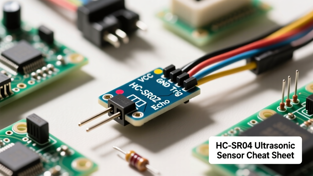
Root Cause: You bought an HY-SRF05 but wired it like an HC-SR04. The HC-SR04 has 4 pins (VCC, Trig, Echo, GND). The HY-SRF05 has 5 pins and requires the 'OUT' pin to be grounded to operate in 3-pin mode, or wired differently for 4-pin mode. Always visually verify the silkscreen on your PCB.
When to Ditch the HC-SR04: Modern Alternatives
The HC-SR04 is a brilliant educational tool and perfectly adequate for indoor, dry, room-temperature projects. However, for commercial or harsh-environment deployments, you should immediately look at its successors:
- JSN-SR04T (Waterproof): Features a sealed, separate transducer probe connected via a 2.5m cable. Ideal for car reverse-radar setups, outdoor weather stations, and sump-pump level monitoring. It uses the exact same timing protocol as the HC-SR04 but eliminates the blind spot down to roughly 20cm.
- RCWL-1601 (mmWave Radar): Uses 24GHz microwave radar instead of sound. It is completely immune to temperature changes, acoustic noise, and soft materials. Crucially, it can read through plastic enclosures, allowing you to hide the sensor entirely inside a waterproof project box without drilling holes for the transducers.
- ToF Sensors (VL53L0X): Uses infrared laser time-of-flight. Provides millimeter accuracy and a pinpoint beam angle (unlike the 15° ultrasonic cone), making it vastly superior for precise robotic arm positioning or conveyor belt object sorting.
By mastering the physics, timing logic, and hardware quirks of the HC-SR04, you build a foundational understanding of sensor polling and signal conditioning that translates directly to these more advanced, modern alternatives.