
The Foundation of DIY Electronics: Understanding Voltage
Whether you are building a custom Arduino-based smart home sensor, wiring a 12V LED lighting rig in your van, or troubleshooting a dead wall outlet, the ability to accurately measure electrical potential is non-negotiable. Checking voltage on multimeter devices is the most fundamental diagnostic skill for any DIYer, electrician, or electronics hobbyist. Yet, the difference between a successful project and a fried component—or worse, a severe electrical shock—often comes down to understanding how and where to measure.
In this comprehensive DIY project guide, we will bypass the generic fluff and dive deep into the exact methodologies for checking voltage on multimeter units. We will cover the critical distinctions between Alternating Current (AC) and Direct Current (DC), decode safety categories (CAT ratings), and provide actionable troubleshooting frameworks for common measurement anomalies like ghost voltage and overload errors.
Decoding the Dial: AC vs. DC Voltage Symbols
Before you touch a single probe to a circuit, you must configure the meter correctly. Modern digital multimeters (DMMs) separate voltage into two distinct modes, usually denoted by specific symbols on the rotary dial:
- V⎓ or VDC (Direct Current): Used for batteries, solar panels, USB power supplies, and microcontrollers (e.g., 5V, 12V, 24V). The current flows in a single, constant direction.
- V~ or VAC (Alternating Current): Used for mains electricity, wall outlets, and household appliances (e.g., 120V in North America, 230V in Europe). The current periodically reverses direction.
Pro Tip: If you are using a manual-ranging multimeter like the Klein Tools MM400, you must also select a range higher than your expected voltage. If you expect 12V from a battery, set the dial to the 20V DC range. Selecting the 2V range will result in an 'OL' (Overload) error, while selecting the 600V range will reduce your decimal precision.
Safety First: CAT Ratings and HRC Fuses
When checking voltage on multimeter devices connected to mains power, the internal build quality of your tool is your only line of defense against arc flashes. The International Electrotechnical Commission (IEC) defines Measurement Categories (CAT) to specify where a meter can be safely used. According to Fluke's official safety guidelines, using a CAT II meter on a CAT III circuit can result in catastrophic failure if a voltage spike occurs.
| CAT Rating | DIY Application Scenario | Example Measurement Point |
|---|---|---|
| CAT II | Plug-in appliances, portable tools | Testing a toaster or power drill cord |
| CAT III | Hardwired equipment, distribution | Wall outlets, lighting ballasts, breaker panels |
| CAT IV | Utility connections, primary supply | Outdoor service entrance, utility meters |
The HRC Fuse Factor: Premium multimeters utilize High Rupturing Capacity (HRC) fuses filled with silica sand. If you accidentally measure voltage while the probes are plugged into the 'Amps' jack (a common and deadly DIY mistake), the HRC fuse safely contains the resulting explosive arc inside the meter casing. Cheap, unbranded $10 multimeters often use standard glass fuses that will shatter, turning the meter into a fragmentation grenade.
Step-by-Step: Checking Voltage on Multimeter for DC Projects
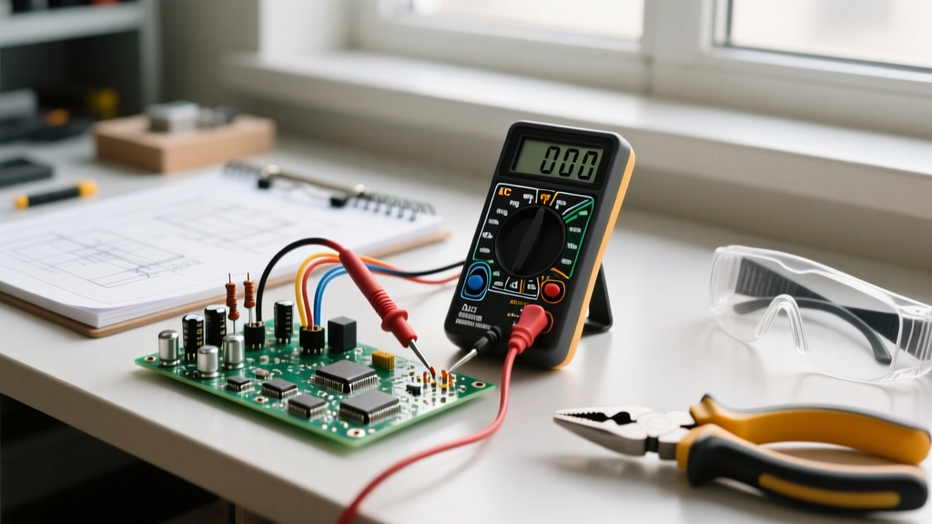
Let us apply this to a common DIY scenario: verifying the output of a 12V DC power supply intended for a custom LED strip installation.
- Probe Placement: Insert the black probe into the COM (Common) port. Insert the red probe into the VΩ (Voltage/Ohms) port.
- Dial Setting: Turn the dial to VDC (or V⎓). If using an auto-ranging meter like the AstroAI AM33D, it will automatically detect the magnitude.
- Connection: Touch the red probe to the positive (+) terminal of the power supply barrel jack or screw terminal. Touch the black probe to the negative (-) terminal.
- Interpretation: A healthy 12V power supply will typically read between 12.1V and 12.6V under no load. If you read 11.4V or lower without any LEDs connected, the power supply has excessive internal resistance and should be replaced to prevent flickering in your DIY project.
Field Note: If your reading displays a negative sign (e.g., -12.2V), do not panic. This simply means your probe polarity is reversed (red on negative, black on positive). Digital multimeters handle reverse polarity gracefully without damage.
Step-by-Step: Checking Voltage on Multimeter for AC Mains
Testing a 120V AC wall outlet requires strict adherence to safety protocols. Never hold the metal tips of the probes; always keep your fingers behind the integrated finger guards.
- Probe Placement: Black to COM, Red to VΩ.
- Dial Setting: Turn the dial to VAC (or V~).
- The 3-Point Receptacle Test:
- Hot to Neutral: Insert red into the shorter slot (Hot) and black into the longer slot (Neutral). Expected reading: 115V - 125V.
- Hot to Ground: Insert red into the shorter slot (Hot) and black into the rounded U-shaped hole (Ground). Expected reading: 115V - 125V.
- Neutral to Ground: Insert red into the longer slot (Neutral) and black into the Ground. Expected reading: 0V - 2V.
- Diagnosis: If your Neutral-to-Ground reading is higher than 2V, you have a 'floating neutral' or excessive voltage drop on the return path, which can cause erratic behavior in sensitive DIY smart-home electronics.
For a deeper dive into the foundational physics and continuity testing, SparkFun's Multimeter Tutorial remains an exceptional resource for beginners bridging the gap between theory and practice.
Troubleshooting Common Voltage Measurement Errors
When checking voltage on multimeter displays, DIYers frequently encounter confusing readings. Here is how to decode and resolve them:
1. The 'OL' (Overload) Error
If your screen flashes 'OL' or '1' on the far left, the voltage exceeds the current range setting. On a manual meter, immediately remove the probes and increase the range (e.g., from 20V to 200V). On an auto-ranging meter, 'OL' means the voltage exceeds the meter's maximum safe input (usually 600V or 1000V).
2. Ghost Voltage and the LoZ Solution
When testing AC wiring in a multi-gang switch box, you might read 40V to 90V on a wire that is supposedly 'dead'. This is ghost voltage, caused by capacitive coupling between parallel live and dead wires in the conduit. Standard high-impedance DMMs amplify this phantom reading. To eliminate it, use a meter with a LoZ (Low Impedance) mode, such as the Fluke 117. LoZ engages an internal shunt resistor that bleeds off capacitive phantom voltage, revealing the true 0V state of the dead wire.
3. Fluctuating or Drifting Readings
If your DC voltage reading slowly climbs or drops erratically, check your probe tips. Oxidation on the metal tips or frayed internal copper stranding in the probe wire introduces variable series resistance. Sand the probe tips lightly with 400-grit sandpaper or replace the test leads entirely.
Recommended Multimeters for DIY Voltage Checks
Selecting the right tool depends on your project scope and budget. Here are three benchmark models for 2026:
- The Professional Standard: Fluke 117 (~$195)
Features True-RMS, LoZ for ghost voltage elimination, and non-contact voltage detection (VoltAlert). Built for CAT III 600V environments. Essential for DIYers doing extensive home wiring or solar installations. - The Prosumer Sweet Spot: Klein Tools MM400 (~$45)
A rugged, manual-ranging meter that survives drops and offers reliable CAT III safety. It lacks auto-ranging and LoZ, but provides exceptional accuracy for automotive and low-voltage electronics projects. - The Budget Bench Tool: AstroAI AM33D (~$15)
Perfect for checking voltage on multimeter setups strictly limited to low-voltage DC (under 50V) like Arduino prototyping or battery testing. Warning: Do not use this tier of meter for AC mains troubleshooting due to inadequate internal arc protection.
Final Thoughts for the DIY Builder
Mastering the art of checking voltage on multimeter devices transforms you from a parts-assembler into a true troubleshooter. By respecting CAT safety ratings, understanding the nuances of AC versus DC, and knowing how to interpret anomalies like ghost voltage, you ensure your DIY projects are not only functional but fundamentally safe. Always verify your meter on a known live source before testing a suspect circuit—a habit that will save your equipment, and potentially your life.