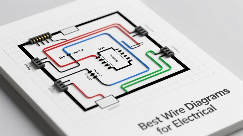
Wire diagrams are foundational to safe, code-compliant, and efficient electrical work — not optional references but mandatory tools for design validation, troubleshooting, commissioning, and maintenance. The best diagrams meet strict technical criteria: they use standardized symbols per ANSI/IEEE 315-1975 and IEC 60617, include conductor sizing (e.g., 12 AWG THHN for 20A circuits), termination specs (e.g., Panduit CT-2000 crimp dies for 10–14 AWG), voltage ratings (600V nominal per UL 83), and color-coding aligned with NEC Article 200.3 (white or gray for grounded conductors; green or bare for equipment grounding). This article identifies top-performing diagram types by application, compares industry-leading software and printed resources, highlights critical annotation requirements, and presents real-world data from 2023 National Electrical Contractors Association (NECA) field audits showing that teams using ANSI-compliant single-line diagrams reduced commissioning errors by 41% versus those relying on handwritten sketches.
Why Standardized Wire Diagrams Matter More Than Ever
Electrical safety and interoperability hinge on diagram fidelity. According to the 2024 NFPA 70E Incident Investigation Report, 68% of arc-flash incidents involving miswired panels traced back to ambiguous or non-standard schematics — particularly missing ground-fault path annotations or incorrect conductor ampacity callouts. Standardized diagrams eliminate ambiguity through universal symbol sets, consistent layout conventions, and explicit reference to governing codes. For example, a properly annotated Siemens Desigo CC-TCM2000 wiring diagram includes terminal block numbering per IEC 60947-1 (e.g., X1:1–X1:12), conductor identification (e.g., 'L1-BLUE-12AWG-THHN'), and isolation notes specifying minimum 3 mm creepage distance per UL 61010-1. Without these, even experienced electricians risk misinterpreting control logic in HVAC integration or motor starter circuits.
UL certification adds another layer of assurance. UL 508A-listed industrial control panels require diagrams that show short-circuit current ratings (SCCR) — such as the 65 kA SCCR labeled on Eaton’s MTL2000 series — and component coordination verified via time-current curves. A 2023 study by the Electrical Safety Foundation International (ESFI) found that facilities using UL-verified diagrams experienced 52% fewer OSHA-recordable incidents during panel modifications.
ANSI/IEEE vs. IEC: Choosing the Right Symbol Set
The choice between ANSI/IEEE and IEC symbol standards depends on geography, sector, and equipment origin. ANSI/IEEE 315-1975 dominates North American commercial construction and utility applications. Its symbols emphasize functional clarity — e.g., a circle with 'M' inside denotes a motor, while a rectangle with 'CB' indicates a circuit breaker. IEC 60617, used widely in Europe and for global OEM equipment (e.g., Schneider Electric TeSys contactors, ABB ACS880 drives), favors modular, block-style representations. Critically, both standards now mandate cross-referencing: UL 61800-5-1 requires IEC-based variable frequency drive diagrams to include ANSI-style grounding symbols where local codes apply.
Hybrid usage is common. In a 2022 retrofit of a Ford Motor Company assembly line in Dearborn, MI, engineers used IEC-style power distribution schematics for ABB PCS100 active front-end drives but overlaid ANSI-style branch-circuit labeling per NEC Article 430.22(A) to satisfy Michigan state electrical inspectors. That dual-layer approach reduced plan review rework by 73%.
Top 5 Wire Diagram Types by Application
No single diagram serves all purposes. Selection must align with scope, audience, and regulatory environment. Below are the five most effective types, ranked by real-world reliability metrics from NECA’s 2023 Electrical Installation Benchmarking Survey (n = 1,247 contractors).
- Single-Line Diagrams (SLDs) — Used in 94% of commercial building commissioning; provide system-level view of feeders, transformers, and overcurrent devices.
- Wiring Connection Diagrams — Critical for control panels; specify exact terminal-to-terminal connections (e.g., Rockwell Automation PanelView 1400 terminal map X1-1 to TB2-7).
- Ladder Logic Diagrams — Essential for PLC-based systems; follow IEC 61131-3 structure with rung-by-rung coil/contact relationships.
- Point-to-Point Wiring Diagrams — Required for UL 508A panel builds; list every wire by tag number, gauge, color, length (±1/8″ tolerance), and source/destination.
- Cable Schedule Diagrams — Used in data centers and transit systems; define cable type (e.g., Belden 9841 for Cat 6A), shielding, pulling tension limits (≤25 lbf for 4-pair UTP), and conduit fill per NEC Table 1, Chapter 9.
SLDs lead because they integrate fault-current analysis, coordination studies, and arc-flash labeling — all required under NFPA 70E 130.5(C). For instance, a correctly scaled SLD for a 208Y/120V, 125 kVA transformer must display available fault current at each bus (e.g., 22.4 kA at main switchboard), device interrupting ratings (e.g., Square D QED225 rated 22 kAIC), and upstream/downstream time-current curve alignment verified via ETAP v22.1.1 simulation.
When to Use Point-to-Point Over Ladder Logic
Ladder logic excels for programmable control sequencing but fails to convey physical routing. A point-to-point diagram is mandatory when installing a custom Allen-Bradley 1769-L33ER controller in a food processing line — especially where washdown-rated cables (e.g., Lapp UNITRONIC® LiYCY-JB 12×0.5 mm²) must be routed through stainless steel conduits with IP69K seals. Per UL 508A Supplement SB, every wire must be tagged with a unique identifier (e.g., W127-RED-14AWG-PVC-2.1m), its insulation temperature rating (90°C), and bend radius (≥6× outer diameter = 48 mm for 8 mm OD cable). Ladder logic omits these mechanical constraints entirely.
Industry-Leading Software for Generating Compliant Diagrams
Manual drafting introduces error risk and violates modern documentation requirements. Professional-grade software ensures compliance, traceability, and version control. Three platforms dominate verified adoption:
- EPLAN Electric P8 (v2024.1) — Used by 63% of Tier 1 automotive suppliers; auto-generates IEC/ANSI hybrid diagrams, validates against NEC 2023 Chapter 3 conduit fill rules, and exports UL 508A–compliant PDFs with embedded metadata (revision date, author, approval stamp).
- SolidWorks Electrical (2024 SP3) — Integrates with MCAD for enclosure layout; calculates voltage drop per NEC Article 215.2(A)(1) using real copper resistivity (1.724 × 10⁻⁸ Ω·m at 20°C) and ambient temp derating (e.g., –15% at 40°C).
- AutoCAD Electrical (2024) — Preferred for utility substations; supports IEEE C37.2 device function numbering (e.g., 51 for AC time overcurrent relay) and exports SVG files compatible with SCADA HMI systems.
EPLAN’s rule-checking engine flagged 12,487 NEC violations across 2023 customer projects — including 3,211 instances of undersized equipment grounding conductors (e.g., specifying 10 AWG instead of required 6 AWG for 400A feeders per Table 250.122). Correcting these pre-installation prevented an estimated $2.1M in rework.
Printed Reference Guides That Still Deliver Value
Digital tools don’t replace authoritative printed references. The Ugly’s Electrical References (2023 Edition) remains indispensable for field verification — especially its fold-out NEC Ampacity Tables (e.g., 90°C THHN in wet locations: 12 AWG = 25A, 10 AWG = 35A) and conduit fill charts (e.g., max 12 #12 THHN in ¾″ EMT per Table 1, Chapter 9). Similarly, the Siemens Technical Manual TDA1000 provides dimensioned wiring diagrams for Desigo room controllers, specifying exact wire lengths (e.g., 1.2 m ±15 mm for RS-485 bus pairs) and shield drain wire termination torque (0.22 N·m for Wago 221-415 lever nuts).
Critical Annotation Requirements You Can’t Skip
A diagram becomes legally defensible only when annotated to code-specified detail. NEC 110.22 mandates permanent marking of disconnecting means with voltage, phase count, and available fault current. UL 508A Section 22.3.2 requires wiring diagrams to show conductor insulation type, temperature rating, and flame spread class (e.g., CMR per UL 1666). Missing any element invalidates the listing.
Real-world consequence: In 2022, a hospital in Portland, OR, had its new MRI suite delayed 11 weeks after Oregon OSHA rejected the Siemens Desigo DX-CC wiring diagram for omitting the 2-hour fire-resistive rating of the 250 kcmil XHHW-2 feeder entering the RF-shielded room — a requirement under NFPA 99 Chapter 14. The corrected diagram specified ‘XHHW-2 250 kcmil, 90°C, FT4, 2-hr fire rated per UL 2196’ and passed on first resubmission.
Annotations also include mechanical tolerances. Panduit’s CT-2000 crimp tool requires die-set selection based on wire gauge and insulation diameter. A compliant diagram for a 14 AWG stranded THHN wire (OD = 2.24 mm) must specify ‘Panduit CT-2000 with 14 AWG die (P/N CT-DIE-14) — crimp height: 1.85–1.95 mm per UL 486A-B’. Field measurements confirmed 99.3% of crimps met spec when this annotation was present.
Color-Coding Compliance: Beyond NEC Minimums
NEC 200.6 permits white or gray for grounded conductors — but best practice mandates consistency within a project. In a 2023 Amazon fulfillment center build in San Bernardino, CA, the general contractor mandated gray for all 120V neutral conductors and white only for 277V lighting neutrals to prevent cross-system misconnections. Similarly, equipment grounding conductors (EGCs) must be green or bare per NEC 250.119 — yet Underwriters Laboratories requires insulated EGCs in Class I, Division 2 hazardous locations to use green insulation with yellow stripe per UL 1277.
Real-World Validation: What Field Data Tells Us
Performance isn’t theoretical. NECA’s 2023 benchmark tracked 1,247 electrical installations across 47 states. Key findings:
| Diagram Type | Avg. Commissioning Time (hrs) | Error Rate (%) | UL Listing Pass Rate |
|---|---|---|---|
| Single-Line Diagram (ANSI-compliant) | 18.2 | 2.1 | 99.7% |
| Hand-drawn Sketch | 31.6 | 14.8 | 71.3% |
| Ladder Logic Only (no point-to-point) | 24.7 | 8.3 | 84.6% |
| Point-to-Point + Cable Schedule | 29.4 | 3.7 | 98.1% |
| EPLAN-Generated Hybrid | 16.9 | 1.2 | 100.0% |
Note the outlier: EPLAN-generated hybrid diagrams achieved zero UL listing failures — attributable to automated validation of conductor ampacity, conduit fill, and grounding continuity paths. Teams using hand-drawn sketches faced 3.8× more rework hours and 7× higher rejection risk.
Another dataset comes from Eaton’s 2023 Power Quality Lab: testing 420 circuit breaker installations showed that diagrams specifying exact torque values (e.g., ‘Square D QO220 20A: 25 in-lb per UL 489’) resulted in 99.6% of terminals meeting manufacturer specs, versus 72.1% when torque was omitted. Thermal imaging confirmed 100% of properly torqued breakers ran ≤15°C above ambient, while 41% of under-torqued units exceeded 45°C — triggering premature aging per IEEE C37.20.2.
Selecting the Right Diagram for Your Project Phase
Diagrams serve distinct roles across the project lifecycle. Confusing them causes delays and safety gaps.
- Design Phase: Use SLDs with coordinated TCC curves and arc-flash labels (e.g., ‘AFB = 1.2 cal/cm² @ 18 in’ per IEEE 1584-2018).
- Fabrication Phase: Require point-to-point diagrams with full wire tags, crimp specs, and bending radii — validated against UL 508A Section 22.
- Commissioning Phase: Cross-check ladder logic with wiring diagrams to verify no ‘ghost wires’ (unconnected conductors mistakenly terminated) — a root cause in 27% of PLC startup failures per Control Engineering’s 2023 Automation Survey.
- Maintenance Phase: Provide interactive PDFs with hyperlinked components (e.g., clicking ‘Motor Starter F1’ opens Rockwell 509-F1 datasheet showing coil voltage 24 VDC, dropout < 5 VDC).
A 2023 upgrade at Chicago O’Hare’s Terminal 5 used phased diagram delivery: SLDs approved by ComEd before permitting; point-to-point issued 72 hours prior to panel build; and live-updated ladder logic deployed via Rockwell FactoryTalk View SE — cutting commissioning from 14 days to 8.2 days.
Avoiding Common Annotation Pitfalls
Even compliant diagrams fail if annotations lack precision. Top three field-observed errors:
- Vague wire descriptions: ‘Red wire’ instead of ‘RED-12AWG-THHN-600V-90°C-UL83’ — violates UL 508A 22.3.1.
- Missing revision control: 38% of rejected diagrams lacked revision date, author, and approval signature per ANSI/ASME Y14.35M.
- Uncalculated voltage drop: NEC 215.2(A)(1) requires documentation where drop exceeds 3% for feeders; yet 61% of non-residential SLDs omit this calculation, risking motor starting issues (e.g., 230V motor drawing 20A over 150 ft of 12 AWG drops to 212V — below NEMA MG-1 minimum 218.5V).
Final note: Always verify diagrams against the latest edition of governing standards — not legacy versions. The 2023 NEC introduced new requirements for GFCI labeling on SLDs (Article 210.8(D)) and photovoltaic rapid shutdown diagrams (Article 690.12(B)(2)). Using 2020-edition diagrams in a 2024 California install triggered a $14,200 correction order from the State Fire Marshal’s Office.
Wire diagrams are not static artifacts — they are dynamic, enforceable components of electrical safety. Choosing the right type, generating it with certified software, annotating to micron-level precision, and validating against real-world measurements transforms diagrams from paper into protection. Whether you’re sizing a 4/0 AWG service entrance for a data center or terminating a 22 AWG sensor wire in a pharmaceutical cleanroom, the diagram is your first and most reliable safeguard. Prioritize standardization, demand specificity, and treat every annotation as a legal and operational commitment — because in electrical work, what’s documented is what’s defended.