
The Reality of AC Alternating Current in Modern Circuits
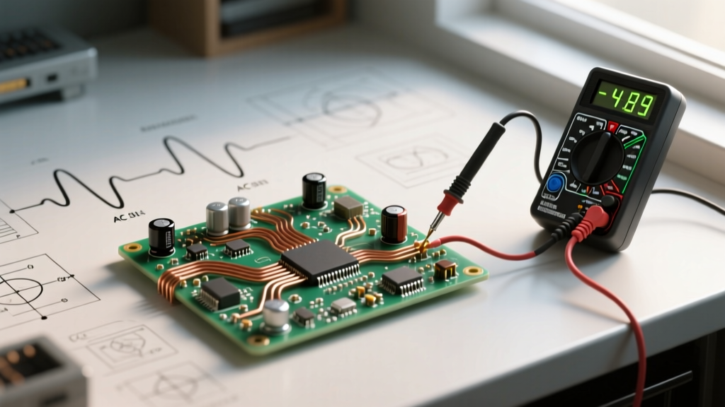
When textbooks introduce AC alternating current, they typically illustrate a pristine, symmetrical sine wave oscillating at exactly 60Hz (or 50Hz). However, in modern DIY electronics, residential wiring, and light commercial setups, this ideal waveform rarely exists. The proliferation of non-linear loads—such as switch-mode power supplies (SMPS), variable frequency drives (VFDs), and LED drivers—has fundamentally altered the AC power environment. Troubleshooting AC circuits today requires an understanding of waveform distortion, harmonic accumulation, and high-impedance coupling.
As a DIYer or electrical hobbyist, misdiagnosing an AC fault can lead to undersized conductors, overheated neutral buses, or catastrophic component failure. This guide dives deep into the practical troubleshooting of AC alternating current anomalies, equipping you with the diagnostic frameworks used by professional power quality engineers.
Essential Diagnostic Toolkit for AC Mains
You cannot troubleshoot what you cannot accurately measure. Standard multimeters often fail when confronted with modern AC waveforms, leading to dangerous miscalculations in wire sizing and breaker selection.
True-RMS vs. Average-Responding Meters
An average-responding multimeter assumes the AC alternating current waveform is a perfect sine wave. It measures the rectified average and multiplies it by a form factor (1.11) to display the RMS value. If the waveform is clipped or distorted by a dimmer switch or VFD, an average-responding meter will yield errors of up to 40%. For accurate troubleshooting, you must use a True-RMS (Root Mean Square) meter, such as the Fluke 87V or Fluke T6-1000, which calculates the actual heating value of the distorted AC wave. For a deeper dive into measurement physics, refer to Fluke's guide on True-RMS measurements.
Low-Impedance (LoZ) Testing
Digital multimeters (DMMs) possess high input impedance (typically 10 MΩ). While great for sensitive DC electronics, this high impedance makes the meter susceptible to capacitive coupling in AC wiring, resulting in 'phantom voltage' readings. Troubleshooting requires a meter with a LoZ (Low Impedance) mode to bleed off this coupled voltage and reveal the true state of the circuit.
Top 4 AC Alternating Current Faults and Solutions
1. Phantom Voltage and Capacitive Coupling
The Symptom: You test a disconnected or open-neutral wire in a multi-conductor Romex cable and read 40V to 90V AC, leading you to believe the circuit is still live or suffering from a backfeed.
The Root Cause: AC alternating current creates an alternating electromagnetic field. When a de-energized wire runs parallel to an energized wire within the same cable jacket, the capacitance between the two conductors couples a small amount of AC voltage onto the dead wire. Because a standard DMM draws almost zero current, it displays this induced phantom voltage.
The Solution: Switch your DMM to LoZ mode, or place a 10kΩ load resistor across the meter probes. If the voltage drops to near zero, it is phantom voltage. No wiring repair is necessary. For more on this phenomenon, see Fluke's article on phantom voltage.
2. Triplen Harmonics and Neutral Overheating
The Symptom: The neutral conductor in a 120/240V split-phase or 208Y/120V three-phase system is running hotter than the phase conductors, or the neutral bus bar is showing signs of thermal discoloration, despite the phase currents being balanced.
The Root Cause: Non-linear loads draw current in abrupt pulses rather than a smooth sine wave. This creates harmonic frequencies. 'Triplen' harmonics (3rd, 9th, 15th) are particularly destructive in AC systems because they are zero-sequence; they do not cancel out on the neutral. Instead, they add up arithmetically. In severe cases, the neutral current can exceed the phase current by 1.73 times.
The Solution: When sizing the neutral wire for circuits heavily loaded with SMPS (like server racks or extensive LED lighting arrays), you must upsize the neutral conductor. While National Fire Protection Association (NFPA) NEC guidelines traditionally allow the neutral to be the same size as the phase in standard residential wiring, engineering best practices for high-harmonic environments dictate sizing the neutral at 200% of the phase conductor ampacity.
3. Voltage Sag from High Inrush Currents
The Symptom: Lights dim momentarily when a DIY workshop air compressor or table saw starts. Microcontrollers on the same AC branch reset unexpectedly.
The Root Cause: Induction motors require massive inrush currents (Locked Rotor Amps or LRA) to establish their magnetic fields—often 6 to 8 times their full-load running amps. If the AC branch circuit wiring is sized only for the running current (e.g., 14 AWG for a 15A circuit), the impedance of the wire causes a severe voltage drop during the startup transient.
The Solution: Calculate the voltage drop based on the LRA, not the FLA (Full Load Amps). For long wire runs in DIY workshops, upsizing the conductors from 12 AWG to 10 AWG or even 8 AWG reduces the AC impedance, mitigating the voltage sag and protecting sensitive microcontrollers from brownout resets.
4. Neutral-to-Ground Voltage (NGV) Anomalies
The Symptom: Audio equipment hums, serial communication (RS-485) drops packets, or you measure more than 2V AC between the neutral and ground receptacle slots.
The Root Cause: According to NEC rules, neutral and ground are bonded only at the main service disconnect. Downstream, the neutral carries return current, and because wire has resistance, Ohm's Law dictates a voltage drop along the neutral. If the circuit is overloaded or the wire is undersized, the NGV rises. Ground loops occur when multiple paths to ground allow AC stray currents to flow through signal cable shields.
The Solution: Measure the NGV under full load. If it exceeds 2V AC, the branch circuit is overloaded or the wire run is too long. Relocate the sensitive electronics to a dedicated 20A circuit with 10 AWG wire to minimize neutral impedance.
AC Alternating Current Troubleshooting Matrix
| Anomaly | Waveform / Meter Signature | Primary Culprit | Corrective Action |
|---|---|---|---|
| Phantom Voltage | 40V-90V AC on dead wire; drops to 0V in LoZ | Capacitive coupling in multi-conductor cables | Verify with LoZ mode; no physical repair needed |
| Triplen Harmonics | Neutral current > Phase current; distorted sine wave | Switch-mode power supplies, LED drivers | Upsize neutral conductor; use K-rated transformers |
| Inrush Voltage Sag | Momentary 15-30% drop in RMS voltage | High LRA induction motors on undersized wire | Upsize phase conductors to reduce AC impedance |
| Elevated NGV | > 2.0V AC between Neutral and Ground | Overloaded neutral; long wire runs; loose bus bar | Tighten connections; dedicate circuit; upsize wire |
Safety Protocols: Respecting the Arc Flash Boundary
Troubleshooting live AC alternating current circuits exposes you to lethal fault currents and arc flash hazards. Never use a standard electronics oscilloscope or a CAT II rated multimeter to probe mains AC distribution panels.
Expert Safety Directive: Always ensure your test equipment carries an independent safety rating (e.g., UL, CSA, or TÜV) of at least CAT III 1000V or CAT IV 600V when probing AC mains at the service entrance or main distribution board. The CAT rating defines the tool's ability to survive high-energy transient voltage spikes (impulses) that occur when AC utility lines switch or when large inductive loads drop offline.
Furthermore, when measuring AC current, avoid breaking the circuit to insert an inline ammeter. Utilize a clamp meter with a flexible Rogowski coil or a Hall-effect sensor to measure the magnetic field around the AC conductor safely. This prevents accidental short circuits and keeps you outside the immediate arc flash boundary.
Conclusion
Troubleshooting AC alternating current faults requires moving beyond basic continuity checks. By understanding the impact of non-linear loads on sine waves, utilizing True-RMS and LoZ diagnostic tools, and respecting the physical limitations of wire impedance during inrush events, you can build and maintain DIY electrical systems that are both robust and safe. Always cross-reference your wire sizing calculations with the latest NEC ampacity tables and prioritize safety-rated test equipment when probing live AC mains.