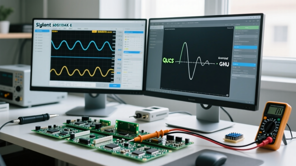

Transitioning from a standalone benchtop oscilloscope to a PC-tethered setup is a rite of passage for many electronics hobbyists and engineering students. While a physical screen and knobs offer tactile satisfaction, oscilloscope software unlocks a realm of possibilities that budget standalone scopes simply cannot match: massive screen real estate, deep memory analysis, advanced Fast Fourier Transform (FFT) processing, and automated serial protocol decoding.
If you are a beginner looking to maximize your lab's capabilities without spending thousands of dollars, understanding how to leverage PC-based oscilloscope software is critical. This guide will walk you through the ecosystem, highlight hidden hardware bottlenecks, and provide a step-by-step tutorial on setting up open-source analysis tools.
The PC Advantage: Why Tether Your Scope?
Before diving into specific software platforms, it is essential to understand why you would want to route your waveform data to a computer in the first place. Budget standalone oscilloscopes (like the popular Rigol DS1054Z or Siglent SDS1202X-E) typically feature 7-inch to 9-inch displays. While adequate for basic triggering, these screens become a major limitation when you need to:
- Decode complex serial buses: Viewing long I2C, SPI, or UART transactions requires horizontal scrolling that is incredibly cumbersome on a small hardware screen.
- Perform deep-memory FFTs: Software can leverage your PC's RAM and CPU to perform high-resolution spectral analysis that would freeze a budget scope's embedded ARM processor.
- Export and document: Capturing high-resolution PNGs, CSVs, and binary dumps directly to your PC's hard drive streamlines the documentation process for DIY blogs and university lab reports.
Hardware vs. Software: Understanding the Ecosystem
Not all oscilloscope software is created equal. The software you use is strictly dictated by the hardware front-end you own. Below is a comparison of the most common PC-based oscilloscope software platforms available to beginners and intermediate makers.
| Software Platform | Compatible Hardware | Cost | Best Feature | Learning Curve |
|---|---|---|---|---|
| PicoScope 6/7 | PicoTech USB Scopes (e.g., 2204A) | Free (with HW) | Industry-leading serial decoding & UI | Low |
| EasyScopeX | Siglent SDS Series | Free | Seamless UI sync with physical scope | Low |
| UltraSigma | Rigol DS/MSO Series | Free | Remote SCPI command control | Moderate |
| PulseView (Sigrok) | FX2LA, DSO138, Open-Source HW | Free / Open Source | Multi-protocol decode on $15 hardware | High |
For beginners on a strict budget, the combination of cheap generic USB hardware and PulseView offers the highest information gain per dollar spent. For those who already own a benchtop Siglent or Rigol, tethering it via LAN or USB to their native software is the logical next step.
The Soundcard Scope Trap (A Warning for Beginners)
When searching for 'free oscilloscope software,' beginners often stumble upon soundcard-based scope applications. These programs use your PC's 3.5mm microphone or line-in jack as an analog-to-digital converter (ADC). Do not use these for debugging circuits.
Failure Mode Alert: PC audio inputs are AC-coupled, meaning they physically block DC voltage. Furthermore, they are limited to a ~2V peak-to-peak range and a 20kHz bandwidth. Feeding a 5V microcontroller PWM signal into your laptop's mic jack will not yield a readable waveform; it will likely blow out your motherboard's audio codec. Always use a dedicated USB ADC or a proper benchtop scope.
Step-by-Step: Setting Up Sigrok and PulseView
To demonstrate the power of open-source oscilloscope software, let us walk through setting up PulseView, the official GUI for the Sigrok project. We will assume you are using a generic $15 'FX2' Logic Analyzer/Oscilloscope hybrid (based on the Cypress CY7C68013A chip), a staple in beginner DIY labs.
- Install Zadig (Windows): The FX2 hardware requires a specific USB driver. Download Zadig, plug in your FX2 device, select it from the dropdown, and replace the default driver with
WinUSB. - Download PulseView: Grab the latest stable nightly build from the Sigrok website. The open-source community updates protocol decoders frequently, so newer builds are generally better.
- Configure the Device: Open PulseView, click the device icon in the top left, and select
fx2lafw. Set your sample rate to 1 MHz and the number of samples to 1M (1 million). - Add a Protocol Decoder: Click the decoder icon (looks like a microchip). Select
I2C. Map Channel 0 to SDA and Channel 1 to SCL. - Capture and Analyze: Hit 'Run'. PulseView will ingest the data and overlay human-readable hex values directly over the analog/digital waveforms.
This setup allows a beginner to debug Arduino I2C sensor failures for under $20, a task that would require a $300+ standalone scope with built-in decoding.
USB Bottlenecks and Buffer Realities
A common point of confusion for beginners reading spec sheets is the discrepancy between advertised sample rates and real-world software performance. You might buy a budget USB oscilloscope advertised as '100 MSa/s' (Mega-samples per second), only to find the software drops samples or crashes when you try to capture a long, continuous waveform.
This is not a software bug; it is a USB bandwidth limitation.
- USB 2.0 Limits: Most budget USB scopes use USB 2.0, which has a theoretical maximum bandwidth of 480 Mbps (approx. 40-48 MB/s in real-world continuous streaming).
- The Single-Shot Caveat: A 100 MSa/s scope can only achieve that speed in single-shot mode, where it fills its onboard hardware buffer (often just 512KB or 1MB) and then pauses to transfer the data to the PC software over USB.
- Continuous Streaming: If you want a continuous, rolling waveform on your PC screen, the software is limited by the USB transfer rate. For an 8-bit ADC over USB 2.0, your continuous sample rate will likely cap out around 10 to 20 MSa/s.
When using tethered oscilloscope software, always check the manufacturer's documentation for 'continuous streaming rate' versus 'maximum single-shot rate.' For debugging high-frequency RF or fast switching power supplies, a standalone scope with a deep hardware memory buffer is vastly superior to a USB-tethered setup.
Safety First: Isolation and Ground Loops
When you connect a USB oscilloscope to your PC, you are electrically tying your probe's ground clip to your computer's ground plane. If your PC is plugged into a wall outlet, that ground is tied to your building's earth ground.
If you attempt to probe a non-isolated circuit (like a mains-powered switching power supply or a vintage CRT television) and you accidentally clip the ground lead to a live voltage node, you will create a dead short through your PC's motherboard. This will instantly destroy your USB port, the oscilloscope front-end, and potentially your computer's CPU.
How to Protect Your PC and Software Setup
To safely use PC-based oscilloscope software for probing non-isolated or floating circuits, you must break the ground loop. You can achieve this by:
- Using a USB Isolator: Devices based on the Analog Devices ADUM3160 chip provide galvanic isolation for USB data and power, protecting your PC from high-voltage faults.
- Laptop on Battery: Unplugging your laptop from the mains charger removes the earth ground reference, though this is a temporary and less reliable safety measure.
- Differential Probes: Instead of relying on the software and hardware's single-ended inputs, use a differential probe to measure the voltage difference between two non-ground points safely.
For more foundational knowledge on safely probing circuits, review the SparkFun Oscilloscope Guide, which covers probe attenuation and grounding fundamentals essential for both standalone and software-based workflows.
Conclusion: Choosing Your Software Path
Oscilloscope software transforms a simple waveform capture into a deep analytical workflow. If you have the budget, investing in a PicoTech USB scope with PicoScope 6/7 software provides a seamless, premium experience that rivals $2,000 benchtop units. If you are a student or hobbyist on a budget, mastering open-source tools like PulseView alongside cheap USB ADC hardware will teach you more about digital protocols and signal processing than simply turning the knob on an expensive standalone unit. Always respect USB bandwidth limits, prioritize electrical isolation, and leverage your PC's processing power to decode the invisible signals in your DIY projects.
For further reading on oscilloscope fundamentals and advanced triggering techniques, consult the PicoTech Oscilloscope Basics library.