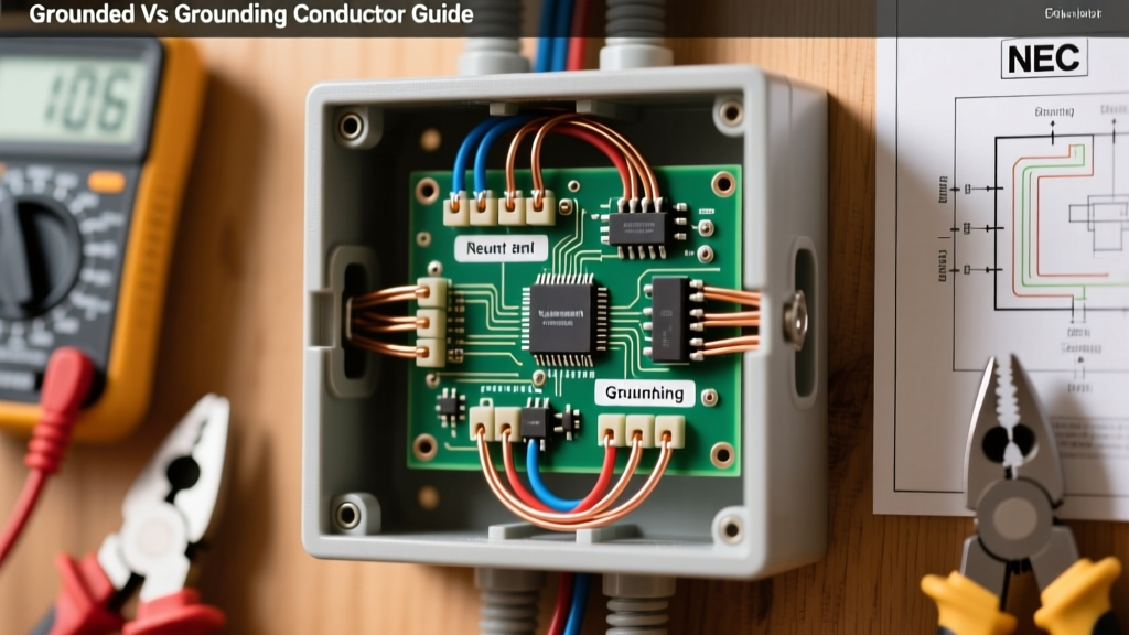

When working with residential or commercial electrical panels, the terminology used in the National Electrical Code (NEC) can be notoriously confusing. Even seasoned DIYers and apprentice electricians frequently mix up the terms grounded conductor and grounding conductor. While they sound nearly identical and both ultimately tie back to the earth, their roles in an electrical circuit are fundamentally different. Confusing the two is not just a semantic error; it is a severe safety hazard that can lead to electrified appliance chassis, stray voltage, and catastrophic shock risks.
In this comprehensive guide, we will break down the grounded vs grounding conductor debate, exploring their distinct functions, NEC sizing requirements, real-world failure modes, and how to troubleshoot them using a digital multimeter.
The Core Distinction: Current Carrying vs. Fault Clearing
To understand the difference, we must look at how electricity flows during normal operation versus how it behaves during a fault condition. The NEC (specifically Article 100) provides strict definitions for these conductors based on their operational intent.
What is a Grounded Conductor?
The grounded conductor is more commonly known as the neutral wire. In a standard single-phase 120V AC circuit, it serves as the designated return path for the current flowing from the hot (ungrounded) conductor. Under normal operating conditions, the grounded conductor carries the exact same amount of current as the hot wire. It is called "grounded" because the utility transformer and the main service panel intentionally connect this conductor to the earth (ground) to stabilize the system voltage and provide a reference point of zero volts.
What is a Grounding Conductor?
The grounding conductor, properly referred to as the Equipment Grounding Conductor (EGC), is the bare copper or green-insulated wire. Under normal operating conditions, the EGC carries absolutely zero current. Its sole purpose is to act as a low-impedance safety shield. If a hot wire breaks loose and touches the metal casing of a refrigerator, the EGC provides a dedicated, highly conductive path back to the panel. This massive surge of fault current instantly trips the circuit breaker, clearing the fault before a human touching the fridge can become the path to ground.
Color Codes, Sizing, and NEC Requirements
Identifying these conductors visually is usually straightforward, but sizing them requires a deep understanding of NEC Chapter 9 and Article 250. Below is a structural comparison of how the National Fire Protection Association (NFPA) categorizes them.
| Feature | Grounded Conductor (Neutral) | Grounding Conductor (EGC) |
|---|---|---|
| Common Name | Neutral | Equipment Ground |
| Standard Insulation | White or Gray | Bare, Green, or Green/Yellow |
| Normal Operation | Carries continuous return current | Carries zero current |
| Fault Operation | Not intended for fault clearing | Carries massive fault current to trip breaker |
| NEC Sizing Rule | Based on calculated load (NEC 220 / 310.15) | Based on breaker rating (NEC Table 250.122) |
The Sizing Math: A 60-Amp Circuit Example
The most common mistake in subpanel wiring is sizing the EGC identically to the grounded conductor. They are sized using entirely different metrics. Let us look at a 60-amp, 240V/120V multi-wire branch circuit or feeder:
- Grounded Conductor (Neutral): If the calculated continuous load on the neutral is only 25 amps, NEC load calculation rules might allow you to downsize the neutral to 10 AWG copper (rated for 30A), provided specific harmonic load conditions are met.
- Grounding Conductor (EGC): The EGC does not care about your continuous load. It cares about the breaker protecting the circuit. According to Mike Holt's NEC resources and NEC Table 250.122, a 60-amp overcurrent device strictly requires a minimum 10 AWG copper EGC. If you upgrade the breaker to 100A, the EGC must jump to 8 AWG copper, even if the actual load remains unchanged.
Real-World Failure Modes: What Happens When They Are Swapped?
Understanding the grounded vs grounding conductor concept is critical because reversing their roles at a receptacle or appliance creates immediate danger.
The "Bootleg Ground" Hazard
In older homes lacking a true EGC, some DIYers attempt to create a fake ground by installing a jumper wire between the neutral (grounded) terminal and the ground (grounding) screw on a 3-prong receptacle. This is known as a bootleg ground.
Why is this lethal? If the neutral wire disconnects anywhere upstream (an "open neutral"), the metal chassis of any plugged-in appliance will immediately rise to 120V. The return current will seek an alternate path, and if you touch the appliance while standing on a damp basement floor, your body completes the circuit. The grounding conductor must never be used as a substitute for a grounded conductor to carry normal load current.
Open Neutral vs. Open Ground
- Open Grounded Conductor (Open Neutral): The device will not function. The 120V circuit is broken. However, the internal wiring of the device remains "hot" and dangerous to touch if exposed.
- Open Grounding Conductor (Open EGC): The device functions perfectly. You will not notice a problem until a catastrophic internal short circuit occurs. Because the EGC is broken, the breaker will not trip, and the metal casing of the device will remain energized at 120V indefinitely.
The Role of the Main Bonding Jumper
A frequent question among electrical students is: "If the neutral and ground both go to the earth, why keep them separate?"
They are bonded together, but only at one specific location: the main service disconnect. Inside your main panel, a piece of metal called the Main Bonding Jumper physically connects the grounded conductor busbar (neutral bar) to the grounding conductor busbar (ground bar) and the metal panel enclosure.
Downstream from this single point—in all subpanels, branch circuits, and receptacles—they must remain strictly isolated. If you bond the neutral and ground bars together in a subpanel, you create parallel neutral paths. Normal return current will split, flowing partially through the neutral wire and partially through the bare copper ground wires, conduit, and plumbing. This causes stray voltage, electromagnetic interference (EMI) in sensitive audio/video equipment, and shock hazards.
Troubleshooting with a Digital Multimeter
You can verify the integrity and separation of the grounded and grounding conductors at any standard 120V duplex receptacle using a high-impedance digital multimeter (DMM), such as those manufactured by Fluke. Set your meter to AC Voltage (V~) and perform the following three tests:
Step-by-Step Receptacle Testing
- Hot to Grounded (Neutral): Insert the red probe into the shorter slot (Hot) and the black probe into the longer slot (Neutral). You should read between 114V and 126V. This confirms the grounded conductor is successfully completing the circuit back to the transformer.
- Hot to Grounding (EGC): Move the black probe to the U-shaped ground hole. You should read the exact same voltage (114V-126V). This proves the EGC is bonded back to the main panel and is capable of clearing a fault.
- Grounded (Neutral) to Grounding (EGC): Measure between the longer slot and the U-shaped hole. Under no-load conditions, this should read 0.0V to 0.5V.
Advanced Diagnostic Insight: If you plug in a high-draw device (like a 1500W space heater) and measure Neutral-to-Ground again, you might see a reading of 1.5V to 3.0V. This is normal. It represents the actual voltage drop occurring across the length of the grounded conductor due to its inherent resistance (Ohm's Law). Because the EGC carries no current, it has zero voltage drop. Therefore, the difference between the two is the voltage drop of the neutral wire. If this reading exceeds 3-5V, your grounded conductor is undersized, corroded, or has a loose termination at the panel.
Summary
Mastering the grounded vs grounding conductor distinction is foundational to electrical safety and code compliance. Remember the golden rule: The grounded conductor (neutral) is a current-carrying workhorse that completes the circuit, while the grounding conductor (EGC) is a silent bodyguard that only acts during an emergency. Never swap them, never bond them downstream of the main service, and always size them according to their specific NEC articles. By respecting the distinct physics and code requirements of each, you ensure a safe, functional, and shock-free electrical system.