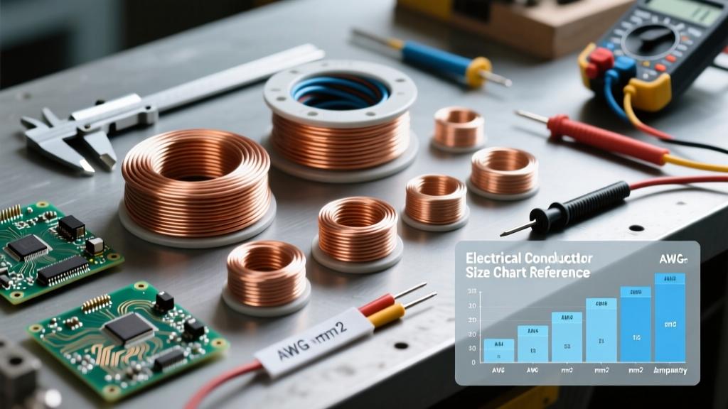

The Master Electrical Conductor Size Chart
Whether you are wiring a new subpanel, sizing feeders for a heavy-duty workshop, or simply replacing a damaged branch circuit, selecting the correct wire gauge is the foundation of electrical safety. The electrical conductor size chart below is based on the National Electrical Code (NEC) Table 310.16, providing the allowable ampacities for copper conductors based on their temperature ratings. Use this as your primary quick reference on the job site or in the DIY workshop.
| AWG Size | Cross-Section (mm²) | Diameter (inches) | 60°C Ampacity (A) | 75°C Ampacity (A) | 90°C Ampacity (A) |
|---|---|---|---|---|---|
| 14 | 2.08 | 0.064 | 15 | 20 | 25 |
| 12 | 3.31 | 0.081 | 20 | 25 | 30 |
| 10 | 5.26 | 0.102 | 30 | 35 | 40 |
| 8 | 8.37 | 0.128 | 40 | 50 | 55 |
| 6 | 13.30 | 0.162 | 55 | 65 | 75 |
| 4 | 21.15 | 0.204 | 70 | 85 | 95 |
| 3 | 26.67 | 0.229 | 85 | 100 | 115 |
| 2 | 33.62 | 0.258 | 95 | 115 | 130 |
| 1 | 42.41 | 0.289 | 110 | 130 | 145 |
| 1/0 | 53.49 | 0.325 | 125 | 150 | 170 |
| 2/0 | 67.43 | 0.365 | 145 | 175 | 195 |
| 3/0 | 85.01 | 0.410 | 165 | 200 | 225 |
| 4/0 | 107.20 | 0.460 | 195 | 230 | 260 |
Note: Ampacities assume an ambient temperature of 30°C (86°F). Derating is required for higher ambient temperatures or when bundling more than three current-carrying conductors in a single raceway.
The 240.4(D) Small Conductor Rule: A Critical Exception
When reading an electrical conductor size chart, many DIYers make a dangerous assumption: because 12 AWG wire has a 90°C ampacity of 30A, they believe they can protect it with a 30A breaker. This is a severe code violation and a fire hazard.
Under NEC Article 240.4(D), small conductors have strict overcurrent protection limits that override their thermal ampacities. Unless specifically exempted (such as for motor starting circuits or air conditioning equipment), the maximum overcurrent device rating for small copper conductors is:
- 14 AWG: Maximum 15 Amps
- 12 AWG: Maximum 20 Amps
- 10 AWG: Maximum 30 Amps
Even if you pull 12 AWG THHN (rated 90°C) through conduit, the breaker protecting that circuit cannot exceed 20A. The 90°C column is primarily used for derating calculations (adjusting for heat or bundling), not for selecting the final breaker size.
Decoding Insulation and the 'Weakest Link' Rule
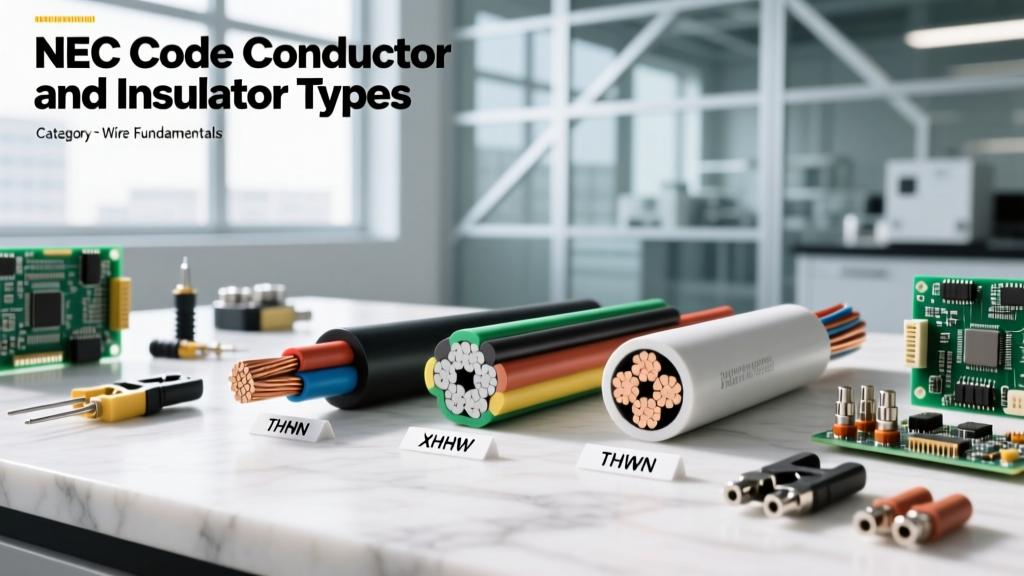
Wire sizing is not just about the copper; it is equally about the insulation jacket. The three temperature columns in the chart above correspond to specific insulation types commonly found in residential and commercial wiring:
60°C Column (NM-B / Romex)
Standard non-metallic sheathed cable (NM-B), commonly known by the brand name Romex, is rated for 60°C. If you are wiring standard 15A or 20A receptacle circuits in residential walls, you must use the 60°C column. Furthermore, Southwire's ampacity guidelines confirm that even if the individual wires inside the NM-B jacket are technically rated higher, the overall assembly is limited to 60°C due to the thermal properties of the outer PVC jacket and the enclosed wall cavity.
75°C Column (THWN / Service Entrances)
Wires rated for wet locations or standard service entrance cables (like SER) typically fall into the 75°C category. This is the standard column used for sizing feeders to subpanels and main service disconnects.
90°C Column (THHN / XHHW-2)
THHN (Thermoplastic High Heat-resistant Nylon-coated) is the standard wire pulled through EMT or PVC conduit in commercial and industrial settings. While it can handle 90°C, you are rarely allowed to use this full ampacity due to termination limits.
NEC 110.14(C): The Termination Bottleneck
The most misunderstood rule in wire sizing is NEC 110.14(C). The code states that the temperature rating of the wire cannot exceed the temperature rating of the termination (the breaker lug or busbar). Most standard residential breakers and busbars are rated for 75°C. Therefore, even if you pull 90°C THHN wire, you must size the wire based on the 75°C column because the breaker lug is the weakest thermal link in the chain.
Voltage Drop: The Silent Ampacity Killer
The electrical conductor size chart guarantees that a wire will not melt or catch fire under a specific load. However, it does not guarantee that your equipment will function correctly over long distances. Voltage drop is the invisible loss of electrical pressure caused by the inherent resistance of the conductor.
According to Engineering Toolbox wire data, copper has a specific resistivity that causes voltage to sag over distance. The NEC recommends (in Informational Notes to Article 210.19 and 215.2) a maximum voltage drop of 3% for branch circuits and 5% for the total feeder and branch circuit combined.
Quick Reference Voltage Drop Formula (Single Phase):
VD = (2 x K x I x L) / CM
- K = 12.9 (for Copper)
- I = Current in Amps
- L = One-way length in feet
- CM = Circular Mils of the conductor (e.g., 10 AWG = 10,380 CM)
Real-World Scenario: If you are wiring a 20A, 120V receptacle at the end of a 150-foot driveway using 12 AWG wire, the voltage drop will be roughly 7.7V (6.4%). This exceeds the 3% recommendation and can cause motors in power tools to overheat and fail prematurely. In this scenario, you must upsize to 10 AWG or even 8 AWG, despite the breaker only requiring 12 AWG for thermal protection.
Copper vs. Aluminum: Sizing for Heavy Feeders
For circuits under 50 Amps, copper is the undisputed standard. However, for heavy feeders (100A to 400A services), aluminum (specifically AA-8000 series alloy) becomes the economic choice. Aluminum is significantly lighter and cheaper than copper, but it has a higher electrical resistance. Consequently, aluminum wire must be sized larger than copper to carry the same ampacity.
For example, to feed a 200A residential service panel:
- Copper: Requires 2/0 AWG (based on 75°C column).
- Aluminum: Requires 4/0 AWG (based on 75°C column).
When using aluminum, you must also apply an antioxidant compound (like Noalox) to the terminations to prevent galvanic corrosion and oxidation, which can lead to high-resistance connections and catastrophic thermal failures over time.
Real-World Failure Modes and Torque Specifications
Sizing the wire correctly via the chart is only half the battle. The most common cause of electrical fires in properly sized circuits is loose terminations. When a wire is not torqued to the manufacturer's exact specification, the contact resistance increases. This generates localized heat, which expands the metal, loosens the screw further, and creates a destructive feedback loop known as thermal runaway.
To combat this, the NEC introduced Article 110.14(D), which mandates the use of calibrated torque tools (torque screwdrivers or wrenches) to tighten terminations to the exact inch-pound specifications listed on the breaker or equipment label. Guessing the tightness or using the 'two-finger wrist flip' method is no longer code-compliant and is a primary cause of melted breaker lugs in subpanels.
Keep this electrical conductor size chart bookmarked, but always remember that wire sizing is a holistic process. You must account for the breaker termination limits, ambient temperature derating, voltage drop over distance, and precise mechanical torque to ensure a safe, code-compliant, and long-lasting electrical installation.