
The Atomic Divide: Core Differences in Electron Mobility
At the most fundamental level of electrical engineering and physics, the ability to distinguish between an insulator and a conductor comes down to atomic structure—specifically, the behavior of valence electrons. In any electrical circuit, current is the directed flow of these electrons. However, not all materials permit this flow equally.
Conductors possess a 'sea of free electrons.' In metallic bonds, the outermost valence electrons are loosely bound to their parent atoms. When an electromotive force (voltage) is applied, these electrons easily detach and drift through the atomic lattice, creating an electrical current. Copper, aluminum, and silver are prime examples, which is why they form the core of almost all wire sizing calculations.
Insulators, conversely, feature tightly bound valence electrons. The energy required to free an electron from its host atom in an insulator is exceptionally high. Under normal operating voltages, virtually zero current flows through an insulator. This property is what allows us to safely route 120V AC or 600V DC conductors through walls without short-circuiting to the framing or electrocuting end-users.
Energy Band Theory: The Physics of Conduction
To truly understand material behavior, electrical engineers rely on Energy Band Theory. This quantum mechanical model divides electron energy levels into two critical bands: the Valence Band (where electrons normally reside) and the Conduction Band (where electrons are free to move and carry current).
- Conductors: The valence and conduction bands overlap. There is no 'band gap' (0 eV). Electrons require virtually no additional energy to enter the conduction band.
- Semiconductors: A small band gap exists (typically 0.5 to 1.5 eV). At absolute zero, they act as insulators, but thermal energy or applied voltage can excite electrons across the gap.
- Insulators: A massive band gap separates the two bands (typically >3 eV, often 5 to 10 eV). Standard voltages cannot provide enough energy to bridge this gap.
For a deeper dive into the quantum mechanics of solid-state materials, the Georgia State University HyperPhysics band theory guide provides an excellent academic foundation.
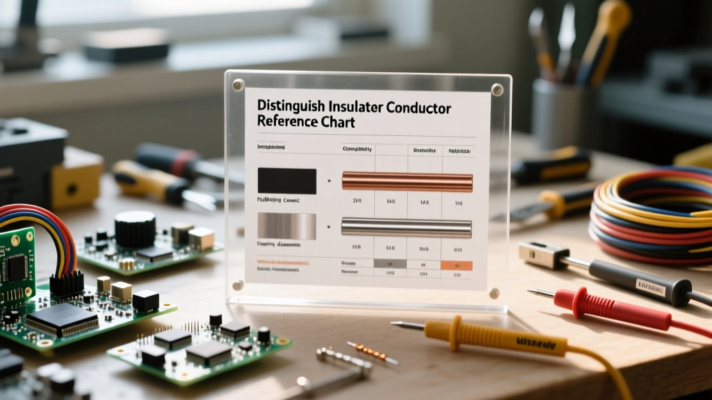
Reference Chart: Resistivity and Conductivity Metrics
When selecting materials for wire sizing or component housing, we quantify these behaviors using electrical resistivity (ρ) and its inverse, conductivity (σ). Resistivity is measured in ohm-meters (Ω·m). The wider the gap in resistivity, the easier it is to distinguish between an insulator and a conductor in a laboratory setting.
| Material | Classification | Resistivity (Ω·m at 20°C) | Band Gap (eV) | Primary Application |
|---|---|---|---|---|
| Silver (Ag) | Conductor | 1.59 × 10⁻⁸ | 0 (Overlap) | High-end audio contacts, RF shielding |
| Copper (Cu) | Conductor | 1.68 × 10⁻⁸ | 0 (Overlap) | Standard branch circuit wiring (THHN) |
| Aluminum (Al) | Conductor | 2.82 × 10⁻⁸ | 0 (Overlap) | Overhead transmission, heavy feeder cables |
| Silicon (Si) | Semiconductor | 2.3 × 10³ | 1.11 | Microcontrollers, solid-state relays |
| Glass (Pyrex) | Insulator | 10¹² to 10¹&sup4; | ~9.0 | High-voltage suspension insulators |
| PTFE (Teflon) | Insulator | > 10¹⁸ | ~8.0 | Aerospace wiring, thermocouple sheaths |
| XLPE | Insulator | > 10¹&sup4; | N/A (Polymer) | Medium/High voltage underground cables |
Source data adapted from the HyperPhysics Wire Properties Table and standard materials science databases.
Dielectric Breakdown: When Insulators Become Conductors
A common misconception among DIYers is that insulators block current absolutely. In reality, every insulator has a threshold known as its dielectric strength. If the applied electric field (voltage per unit thickness) exceeds this threshold, the sheer electromagnetic force rips electrons from their atomic bonds. The insulator violently transitions into a conductor, resulting in an arc flash or short circuit.
Real-World Failure Mode: If you use standard 600V-rated THHN wire (PVC/Nylon insulation) on a 2000V DC solar array, the voltage gradient will exceed the PVC's dielectric strength (typically ~20 kV/mm). The insulation will suffer catastrophic dielectric breakdown, tracking current to the conduit and causing a ground fault or fire.
Dielectric Strength Comparison Chart
| Insulating Material | Dielectric Strength (kV/mm) | Typical Wire Rating |
|---|---|---|
| Air (at STP) | ~3.0 | N/A (Clearance spacing) |
| PVC (Standard) | 15 - 20 | 300V / 600V |
| XLPE | 20 - 30 | 600V to 35kV |
| PTFE (Teflon) | 60 - 100 | 600V to 10kV (Aerospace) |
Practical Field Testing: Identifying Unknown Materials
How do you distinguish between an insulator and a conductor when you find an unmarked wire or material on a job site? You cannot rely on visual inspection alone; carbon-loaded plastics can look identical to pure polymers but possess vastly different conductive properties.
Step 1: The Standard Multimeter Continuity Test
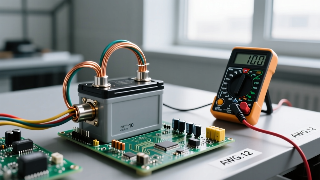
Set your digital multimeter (DMM) to the Ohms (Ω) or continuity setting. Apply the probes to the material. A true conductor will yield a reading near 0 Ω (accounting for lead resistance). An insulator will read 'OL' (Over Limit) or infinite resistance. However, a DMM only applies a tiny voltage (usually <3V). This is insufficient to detect degraded insulation or high-resistance contaminants.
Step 2: Megohmmeter (Megger) Testing for Insulation Integrity
To properly evaluate insulators, professionals use a Megohmmeter. As detailed in Fluke's guide to insulation resistance testing, a Megger applies a high DC voltage (typically 250V, 500V, or 1000V) and measures the microamp leakage current.
- Good Insulator: Reads >100 Megohms (MΩ). The material successfully restricts electron flow even under high electrical stress.
- Degraded Insulator / Semi-Conductor: Reads between 1 MΩ and 10 MΩ. Moisture, carbon tracking, or thermal degradation has compromised the atomic bonds.
- Conductor / Dead Short: Reads < 1 MΩ (or near zero). The material has failed or is inherently conductive.
Summary Matrix: Quick Decision Framework
Use this rapid reference matrix when evaluating materials for your next electrical or electronics project:
| Criteria | Conductor | Insulator |
|---|---|---|
| Primary Function | Carry current with minimal loss | Constrain current to the intended path |
| Valence Electrons | Loosely bound (1-3) | Tightly bound (5-8) |
| Temperature Coefficient | Positive (Resistance increases with heat) | Negative (Resistance decreases with heat) |
| Multimeter Reading | < 1 Ohm | OL (Infinite) |
| Common Examples | Copper, Aluminum, Gold, Silver | PVC, XLPE, Rubber, Glass, Ceramic |
Understanding these fundamental differences ensures that your wire sizing, grounding, and component selections are both safe and compliant with NEC standards. Always verify material properties against manufacturer datasheets before deploying them in high-voltage or high-frequency environments.