
The Short Answer: Dissecting the Copper Wire Anatomy
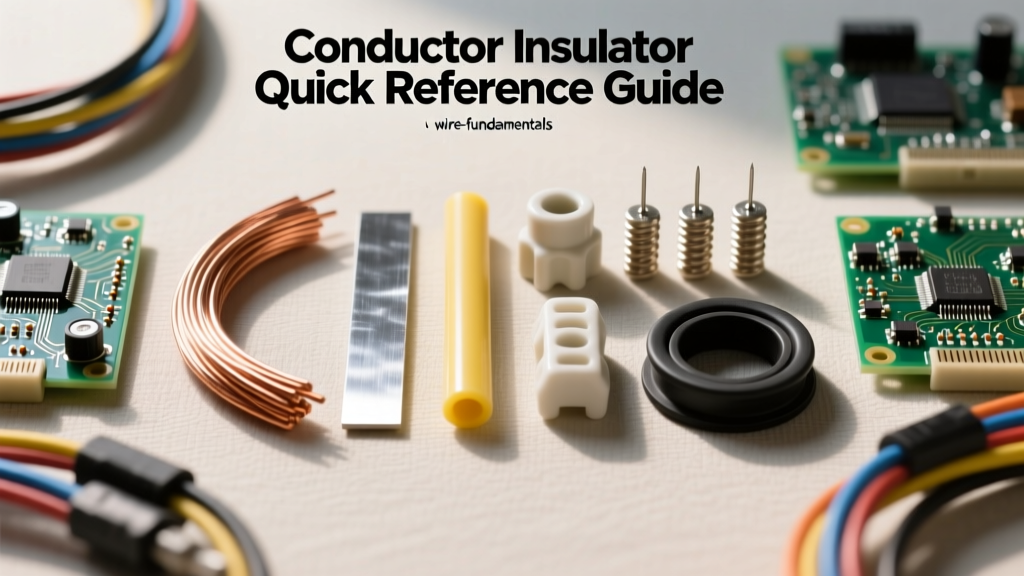
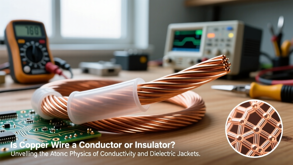
When beginners and DIY enthusiasts ask, 'is copper wire a conductor or insulator?', the confusion almost always stems from a linguistic shortcut. In everyday language, we refer to the entire coated cable as 'wire.' However, in electrical engineering and physics, we must strictly separate the conductor (the bare metal core) from the dielectric jacket (the outer insulating coating).
The definitive answer is that the copper core is a highly efficient conductor, while the outer jacket is the insulator. Bare copper possesses an atomic structure that allows electrons to flow with minimal resistance. Conversely, the materials wrapped around the copper (such as PVC, XLPE, or PTFE) are dielectrics designed to trap electrons and prevent them from escaping the intended circuit path. Understanding the boundary between these two components is critical for safe wire sizing, circuit design, and troubleshooting.
Atomic Physics: Why Bare Copper is an Elite Conductor
To understand why copper is the undisputed global standard for electrical conduction, we have to look at its atomic structure. Copper (Cu) has an atomic number of 29. Its electron configuration is [Ar] 3d10 4s1. That single electron in the outermost 4s orbital is known as a valence electron.
Because this valence electron is located relatively far from the nucleus and is shielded by the inner electron shells, it is very loosely bound to the atom. In a solid piece of copper, these outer electrons detach from their parent atoms and form what physicists call a 'sea of free electrons' or an 'electron gas.' When a voltage potential is applied across the copper wire, this sea of free electrons drifts uniformly, creating an electrical current. According to the Electronics Tutorials database, this atomic configuration gives copper an incredibly low electrical resistivity of approximately 1.68 x 10^-8 Ohm-meters at 20°C.
Conductivity Metrics: Copper vs. Alternatives
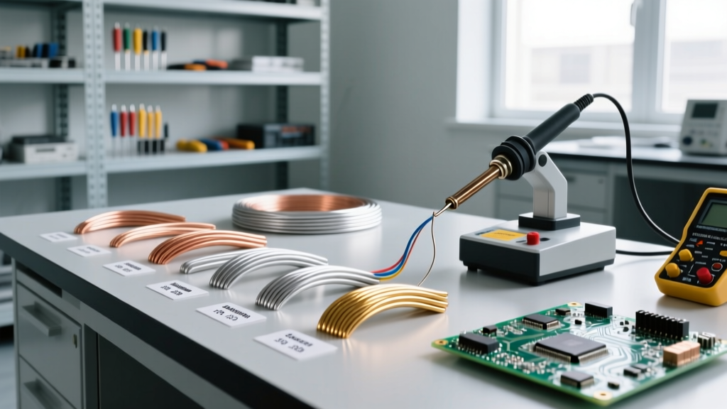
The Copper Development Association (CDA) notes that copper is the baseline by which all other conductors are measured. The International Annealed Copper Standard (IACS) sets annealed copper at exactly 100% conductivity. Here is how it compares to other common metals:
| Metal | IACS Conductivity | Resistivity (nOhm-m) | Primary Use Case |
|---|---|---|---|
| Silver | 105% | 15.9 | High-end audio contacts, aerospace |
| Copper (Annealed) | 100% | 17.2 | Building wire, PCBs, motors |
| Gold | 70% | 24.4 | Corrosion-resistant connector plating |
| Aluminum | 61% | 28.2 | High-voltage overhead transmission |
The Dielectric Shield: Where the 'Insulator' Confusion Begins
If bare copper is the conductor, why do people associate copper wire with insulation? Because bare copper is rarely used in modern infrastructure. Exposed copper would instantly short-circuit against other wires, ground to metal junction boxes, and pose severe electrocution hazards. Therefore, manufacturers extrude a dielectric (insulating) polymer over the copper strands.
The insulator works on the opposite atomic principle of the conductor. Dielectric materials have tightly bound valence electrons with a large 'band gap,' meaning it requires a massive amount of energy to force an electron to break free and conduct electricity. The effectiveness of this insulation is measured by its dielectric strength, typically expressed in kilovolts per millimeter (kV/mm). According to HyperPhysics at Georgia State University, dielectric breakdown occurs when the electric field exceeds the material's capacity, tearing electrons from their atoms and turning the insulator into a temporary conductor (an arc or spark).
Common Jacket Materials and Breakdown Voltages
- PVC (Polyvinyl Chloride): Standard for household THHN wire. Dielectric strength is roughly 40 kV/mm. Rated for 90°C in dry locations.
- XLPE (Cross-Linked Polyethylene): Used in medium and high-voltage underground cables. Superior thermal stability and a dielectric strength around 50 kV/mm.
- PTFE (Teflon): Used in aerospace and high-temperature electronics. Exceptional chemical resistance, rated up to 260°C, with a dielectric strength of 60 kV/mm.
Real-World Failure Modes: When Conductors and Insulators Collide
Understanding the distinction between the copper conductor and the polymer insulator is not just academic; it is vital for diagnosing electrical failures. When the boundary between the two breaks down, catastrophic failure modes occur.
Thermal Degradation and Insulation Meltdown
Copper is an excellent conductor of heat as well as electricity. If a circuit is overloaded, the copper core heats up due to I^2R (current squared times resistance) losses. While the copper itself can withstand temperatures well over 1000°C before melting, the insulator cannot. If a 12 AWG THHN copper wire carries 40 Amps (exceeding its 20A-25A rating), the copper will transfer heat to the PVC jacket. The PVC will soften, melt, and eventually carbonize. Carbon is a conductor. Once the insulation carbonizes, it creates a conductive path to ground or adjacent wires, resulting in an arc fault or fire.
Corona Discharge and Tracking
In high-voltage applications, if the dielectric jacket is scratched or compromised during installation, the electric field concentrates at the tip of the exposed copper conductor. This ionizes the surrounding air, creating a 'corona discharge.' Over time, this UV and ozone-rich environment degrades the surrounding insulation, leading to 'arc tracking'—a permanent, conductive carbon scar across the surface of the insulator that eventually causes a dead short.
Practical Sizing and Selection Framework for DIYers
When selecting and working with copper wire, you must treat the conductor and the insulator as two separate engineering components. Use this framework to ensure safety and longevity in your projects:
- Size the Conductor for Current (Amps): Use the NEC (National Electrical Code) ampacity charts to size the bare copper cross-section. The copper must be thick enough to handle the continuous current without exceeding the temperature rating of the jacket.
- Size the Insulator for Voltage and Environment: Ensure the dielectric jacket's voltage rating (e.g., 600V for standard THHN) exceeds your peak system voltage. Furthermore, match the jacket material to the environment. Use XHHW-2 (XLPE) for wet locations or direct burial, and use Silicone or PTFE for high-heat environments like kilns or engine bays.
- Never Nick the Conductor During Stripping: When stripping the insulator, never use a knife or improper strippers that gouge the copper. A nick in the copper reduces its cross-sectional area at that exact point, creating a localized high-resistance 'hot spot' that will degrade the surrounding insulator over time.
- Test the Insulator with a Megger: If you suspect insulation failure in an older copper circuit, do not use a standard multimeter. A multimeter's 9V battery cannot test dielectric integrity. Use an Insulation Resistance Tester (Megger) which injects 500V to 1000V into the wire to ensure the dielectric barrier is holding strong without leaking current to ground.
Expert Takeaway: Copper is fundamentally a conductor, defined by its free-flowing valence electrons. The 'insulator' is merely the dielectric jacket tasked with containing those electrons. Respecting the physical limits of both the metal core and the polymer shield is the hallmark of professional electrical design.