
The Core Concept: What is Alternating Current?
When beginners first study electrical theory, the phrase alternating current current flow can seem like a redundant stutter. However, it distinguishes the type of system (Alternating Current, or AC) from the physical movement of electrons (current). Unlike Direct Current (DC), where electrons march steadily in a single direction from negative to positive, AC current flow periodically reverses direction. This reversal is not random; it follows a precise, mathematical rhythm that powers everything from your bedroom lamp to heavy industrial manufacturing plants.
To truly grasp AC, we must look past the wall outlet and understand the physics of how this energy is generated, measured, and transmitted through the copper and aluminum conductors we size for our DIY and professional projects.
Physical Generation: Faraday’s Law and the Alternator
Alternating current is born from electromagnetic induction. When a conductive loop of wire rotates through a magnetic field, the changing magnetic flux induces an electromotive force (EMF). According to Faraday’s Law of Induction, as the loop rotates, the angle at which it cuts the magnetic field lines changes continuously.
At 0 degrees, the loop moves parallel to the field, inducing zero voltage. At 90 degrees, it cuts perpendicularly, inducing maximum voltage. By the time it reaches 180 degrees, the loop has flipped, and the voltage polarity reverses. This physical rotation inside an alternator naturally generates a sine wave, the foundational waveform of global power grids. For a deeper dive into the mathematical derivation of these waveforms, the All About Circuits textbook on AC waveforms provides an excellent, rigorous breakdown.
Decoding AC Measurements: Peak vs. RMS
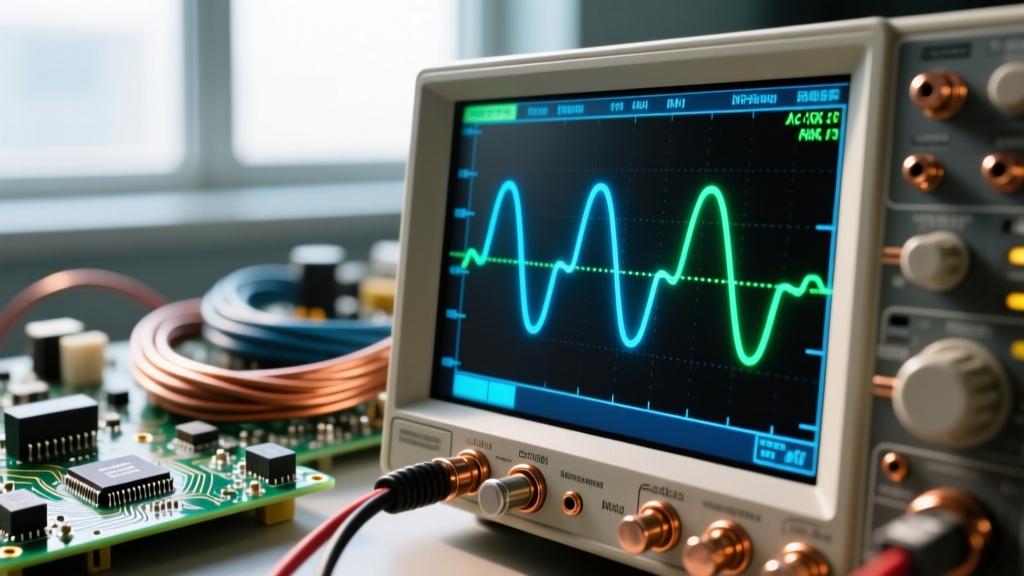
One of the most confusing hurdles for beginners is understanding how we measure a voltage that is constantly changing. If you put an oscilloscope on a standard US wall outlet, you will not see a flat 120V line. You will see a sine wave that peaks at roughly 170V and drops all the way to 0V twice every cycle.
So why do we call it 120V? The answer lies in Root Mean Square (RMS) values. RMS is a statistical method used to express an AC voltage or current in terms of its DC equivalent regarding power delivery and heat generation. If an AC current has an RMS value of 10 Amps, it will produce the exact same amount of heat in a resistive wire as a steady 10 Amp DC current.
Expert Insight: Never size wire insulation or calculate breaker trip curves based on the 'Peak' voltage of an AC circuit. Thermal limits and power dissipation are strictly governed by RMS values. The formula for a pure sine wave is V_RMS = V_Peak / √2 (approximately V_Peak × 0.707).
Standard Global Mains Values
| Region | Nominal RMS Voltage | Peak Voltage | Peak-to-Peak Voltage | Frequency |
|---|---|---|---|---|
| North America (Residential Split-Phase) | 120V / 240V | ~170V / ~340V | 340V / 680V | 60 Hz |
| Europe / UK / Most of Asia | 230V | ~325V | 650V | 50 Hz |
| North America (Commercial 3-Phase Wye) | 208V / 120V | ~294V / ~170V | 588V / 340V | 60 Hz |
For more on the physics of RMS calculations, Georgia State University's HyperPhysics offers a brilliant interactive breakdown of the calculus behind the Root Mean Square.
Frequency and the Hertz (Hz) Factor
Frequency defines how many complete sine wave cycles occur in one second, measured in Hertz (Hz). In North America, the grid operates at 60 Hz, meaning the current changes direction 120 times per second (two zero-crossings per cycle). In Europe, it is 50 Hz.
Why does this matter for DIY electronics and wiring? Frequency dictates the behavior of reactive components (inductors and capacitors) and, crucially, how current distributes itself across the cross-section of a conductor.
How AC Current Flow Impacts Wire Sizing
When sizing wires for DC circuits, current distributes evenly across the entire cross-sectional area of the conductor. If you are using 10 AWG copper wire, the entire 10,380 circular mils of copper is actively carrying the load. AC current flow, however, introduces a phenomenon known as the Skin Effect.
The Skin Effect in AC Wiring
As alternating current flows through a conductor, it generates a changing magnetic field inside the wire. This internal magnetic field induces eddy currents that oppose the main current flow in the center of the conductor, effectively pushing the electrons toward the outer 'skin' of the wire.
The depth at which 63% of the current flows is called the skin depth (δ). Skin depth decreases as frequency increases.
- At 60 Hz (Standard Mains): The skin depth in copper is approximately 8.5 mm. Because the radius of even a massive 4/0 AWG wire is less than 6 mm, the skin effect is practically negligible for standard 60 Hz residential wiring. The entire conductor is utilized.
- At 400 Hz (Aerospace / VFDs): Skin depth drops to about 3.3 mm. Large conductors begin to lose efficiency in their core.
- At 1 MHz (Radio Frequencies / Switching Power Supplies): Skin depth shrinks to a microscopic 0.066 mm. The center of the wire is entirely useless for current flow.
This is why high-frequency applications require specialized Litz wire (multiple individually insulated thin strands braided together) or hollow copper tubing, rather than a single solid thick conductor. For standard 60 Hz home wiring, however, standard solid or stranded THHN copper is perfectly adequate, and the NEC ampacity tables already account for standard AC thermal limits.
AC vs. DC: Arc Extinction and Safety
Understanding alternating current current flow is also a matter of life and death when working with live circuits. One of the primary reasons AC won the 'War of the Currents' against Edison’s DC is its behavior during an electrical fault or arc.
When a switch is opened under load, an arc can form. In a DC circuit, the voltage is constant, meaning the arc can sustain itself indefinitely, melting contacts and causing fires. In an AC circuit, the sine wave naturally passes through zero volts 120 times a second (on a 60 Hz grid). Every time the waveform crosses zero, the arc is momentarily extinguished. This 'zero-crossing' makes AC circuit breakers and switches vastly easier to design and significantly safer to operate, as the arc has a natural opportunity to cool and die out before the voltage ramps back up.
Summary for the DIY Electrician
Mastering the fundamentals of AC current flow bridges the gap between simply following a wiring diagram and truly understanding why the National Electrical Code (NEC) mandates specific practices. Remember that RMS values dictate your thermal wire sizing, the 60 Hz frequency keeps the skin effect at bay for standard AWG sizes, and the zero-crossing nature of the sine wave is what allows your standard breakers to safely interrupt a fault. Always respect the peak voltages hiding behind your RMS multimeter readings, and treat every AC conductor with the caution it demands.